Nissan Maxima Service and Repair Manual: U122A AV control unit
DTC Logic
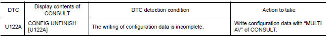
Diagnosis Procedure
1.PERFORM THE SELF-DIAGNOSIS
When U122A is detected, write configuration data with "MULTI AV" of CONSULT.
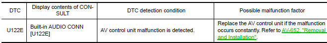
U122E AV CONTROL UNIT
DTC Logic
DTC DETECTION LOGIC
 U121D AV control unit
DTC Logic
Diagnosis Procedure
1.CHECK PLAYBACK OF A DISK (CD)
U121E AV CONTROL UNIT
DTC Logic
Diagnosis Procedure
1.CHECK PLAYBACK OF A DISK (CD)
U1225 AV CONTROL UNIT
DTC Logic
DTC D ...
 U1232 steering angle sensor
DTC Logic
Diagnosis Procedure
1.ADJUST THE PREDICTIVE COURSE LINE CENTER POSITION OF THE STEERING ANGLE
SENSOR
When U1232 is detected, adjust the predictive course line center position of
t ...
Other materials:
Antenna AMP
Removal and Installation
REMOVAL
Remove the rear pillar finisher RH. Refer to INT-27, "Exploded
View".
Detach the antenna amp. harness clip (A).
Disconnect the harness connectors (B) from the antenna amp.
(1).
Remove the antenna amp. screw (C) and the antenna amp. (1).
...
Precaution
PRECAUTIONS
Precaution for Supplemental Restraint System (SRS) "AIR BAG" and "SEAT
BELT
PRE-TENSIONER"
The Supplemental Restraint System such as "AIR BAG" and "SEAT BELT
PRE-TENSIONER", used along
with a front seat belt, helps to reduce the risk or severity of injury to t ...
Exterior front
Engine hood
Wiper and washer switch
Windshield
Power windows
Door locks NISSAN Intelligent Key. Keys
Mirrors. Side view camera (if so equipped)
Tire pressure. Flat tire. Tire chains
Headlight and turn signal switch. Replacing bulbs
Fog light switch. Daytime running light syste ...
Nissan Maxima Owners Manual
- Illustrated table of contents
- Safety-Seats, seat belts and supplemental restraint system
- Instruments and controls
- Pre-driving checks and adjustments
- Monitor, climate, audio, phone and voice recognition systems
- Starting and driving
- In case of emergency
- Appearance and care
- Do-it-yourself
- Maintenance and schedules
- Technical and consumer information
Nissan Maxima Service and Repair Manual

0.0054