Nissan Maxima Service and Repair Manual: U1243 display unit
DTC Logic
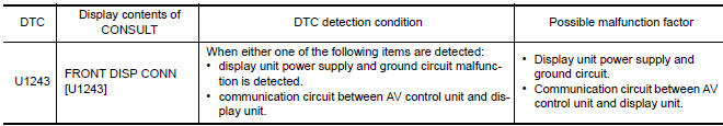
Diagnosis Procedure
1.CHECK DISPLAY UNIT POWER SUPPLY AND GROUND CIRCUIT
Check display unit power supply and ground circuit
2.CHECK CONTINUITY OF COMMUNICATION CIRCUIT
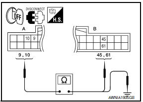
- Turn ignition switch OFF.
- Disconnect display unit connector M142 and AV control unit connector M163.
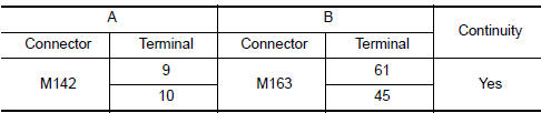
- Check continuity between display unit harness connector M142 (A) terminals 9, 10 and AV control unit harness connector M163 (B) terminals 45 and 61
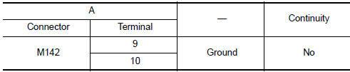
- Check continuity between display unit harness connector M142 (A) terminals 9, 10 and ground.
3.CHECK COMMUNICATION SIGNAL
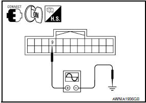
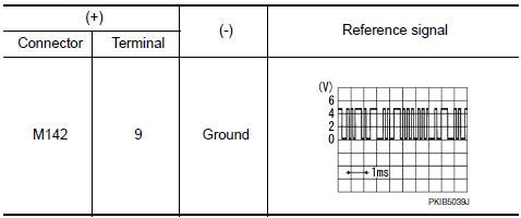
- Connect display unit connector and AV control unit connector.
- Turn ignition switch ON.
- Check signal between display unit harness connector M142 terminal 9 and ground with an oscilloscope or CONSULT
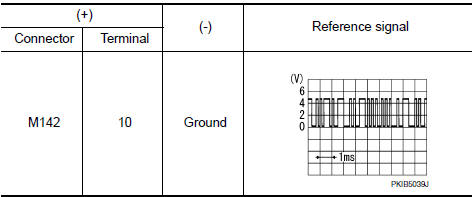
4.CHECK COMMUNICATION SIGNAL
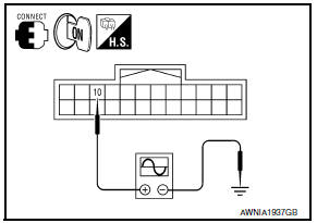
Check signal between display unit harness connector M142 terminal 10 and ground with an oscilloscope or CONSULT.
 U1232 steering angle sensor
DTC Logic
Diagnosis Procedure
1.ADJUST THE PREDICTIVE COURSE LINE CENTER POSITION OF THE STEERING ANGLE
SENSOR
When U1232 is detected, adjust the predictive course line center position of
t ...
 U1244 GPS antenna
DTC Logic
Diagnosis Procedure
1.GPS ANTENNA CHECK
Inspect GPS antenna and antenna feeder for damage or poor connection.
2.CHECK AV CONTROL UNIT VOLTAGE
Turn ignition switch ON.
Check ...
Other materials:
P1723 speed sensor
Description
The secondary speed sensor detects the revolution of
parking gear and generates a pulse signal. The pulse
signal is sent to the TCM, which converts it into vehicle speed.
The primary speed sensor detects the primary pulley revolution speed and sends a
signal to the TCM.
DTC Lo ...
Standardized relay
Description
NORMAL OPEN, NORMAL CLOSED AND MIXED TYPE RELAYS
Relays can mainly be divided into three types: normal open, normal closed and
mixed type relays
TYPE OF STANDARDIZED RELAYS
1M * 1 Make
2M * 2 Make
1T * 1 Transfer
1M*1B * 1 Make 1 Break
...
Emission Control System Maintenance
Drive belts*:
Check engine drive belts for wear, fraying or
cracking and for proper tension. Replace any
damaged drive belts.
Engine air filter:
Replace at specified intervals. When driving for
prolonged periods in dusty conditions,
check/replace the filter more frequently.
Engine coolant*:
...
Nissan Maxima Owners Manual
- Illustrated table of contents
- Safety-Seats, seat belts and supplemental restraint system
- Instruments and controls
- Pre-driving checks and adjustments
- Monitor, climate, audio, phone and voice recognition systems
- Starting and driving
- In case of emergency
- Appearance and care
- Do-it-yourself
- Maintenance and schedules
- Technical and consumer information
Nissan Maxima Service and Repair Manual

0.0092