
Nissan Maxima Service and Repair Manual: Clip list
Descriptions for Clips
Replace any clips which are damaged during removal or installation.
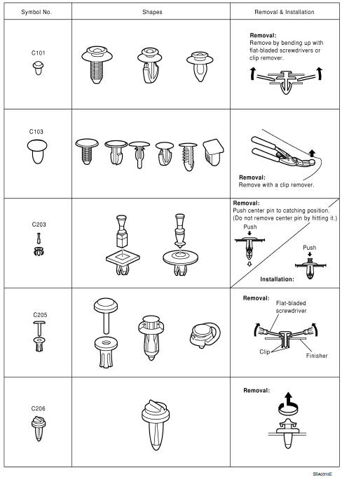
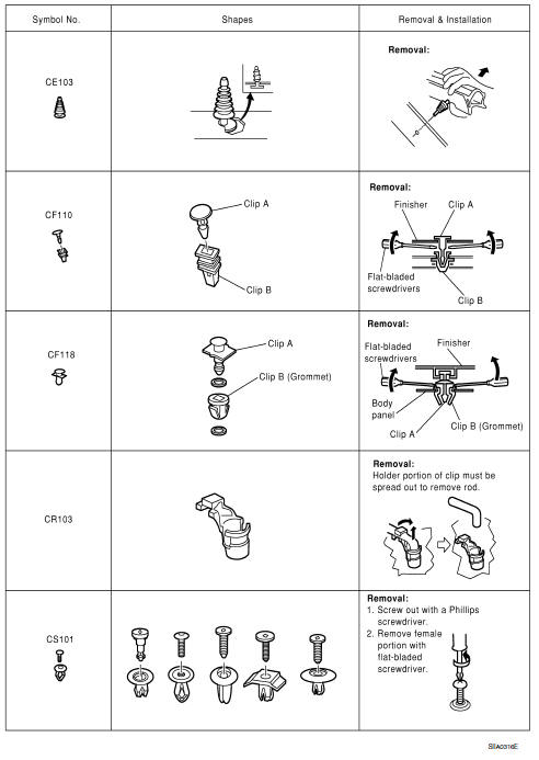
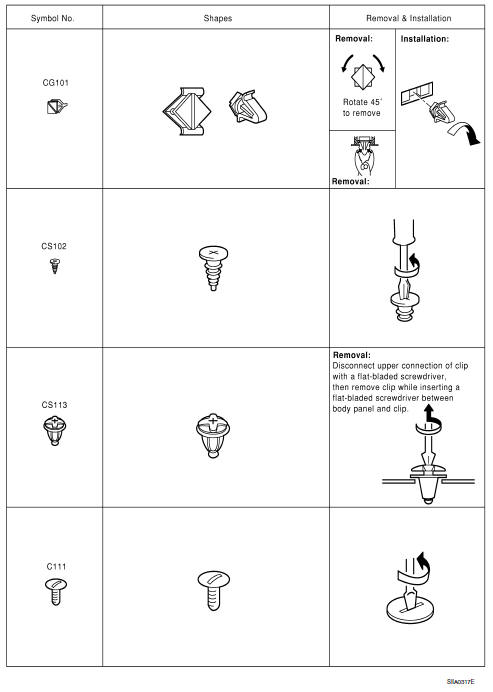
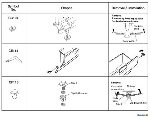
 Preparation
Special Service Tools
...

Other materials:
Combination switch output circuit
Diagnosis Procedure
1. CHECK OUTPUT 1 - 5 SYSTEM CIRCUIT FOR OPEN
Turn the ignition switch OFF.
Disconnect the BCM and combination switch.
Check continuity between BCM harness connector and combination
switch harness connector
2. CHECK OUTPUT 1 - 5 SYSTEM CIRCUIT FOR SHORT
Check ...
Tire pressure receiver
Removal and Installation
REMOVAL
Remove instrument lower panel LH. Refer to IP-11, "Removal and
Installation".
Locate tire pressure receiver (1) to the right of the steering column
and disconnect the harness connector from the tire pressure receiver.
Remove tire pressure receiver ...
Antenna AMP
Removal and Installation
REMOVAL
Remove the rear pillar finisher RH. Refer to INT-23, "Exploded
View".
Detach the antenna amp. harness clip (A).
Disconnect the harness connectors (B) from the antenna amp.
(1).
Remove the antenna amp. screw (C) and the antenna amp. (1).
INSTALLAT ...
Nissan Maxima Owners Manual
- Illustrated table of contents
- Safety-Seats, seat belts and supplemental restraint system
- Instruments and controls
- Pre-driving checks and adjustments
- Monitor, climate, audio, phone and voice recognition systems
- Starting and driving
- In case of emergency
- Appearance and care
- Do-it-yourself
- Maintenance and schedules
- Technical and consumer information
Nissan Maxima Service and Repair Manual

0.014