Nissan Maxima Service and Repair Manual: Preparation
Special Service Tools
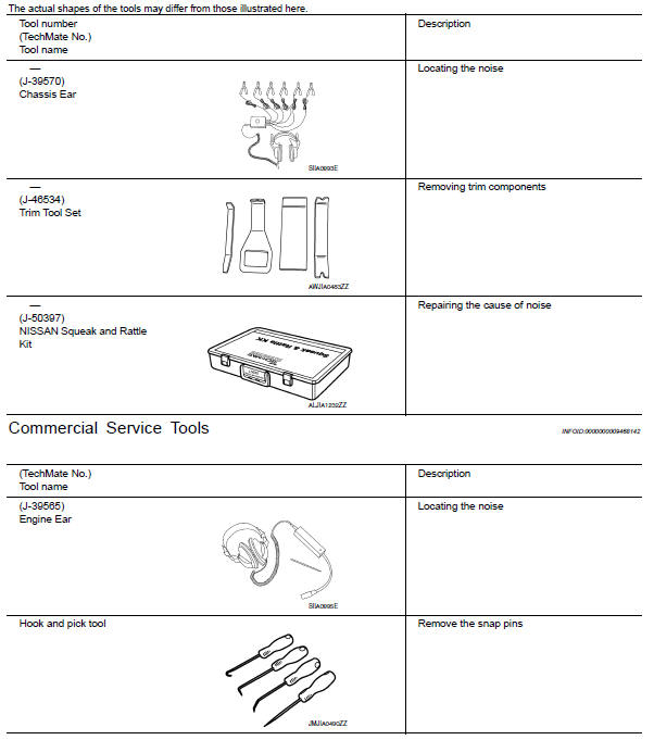
 Preparation
...
 Clip list
Descriptions for Clips
Replace any clips which are damaged during removal or installation.
...
Other materials:
Recommended fluids/lubricants and capacities
The following are approximate capacities. The actual refill capacities may
be slightly different. When refilling, follow the procedure
described in the "Do-it-yourself" section to determine the proper refill
capacity.
...
Trunk lid opener cancel switch
Description
Cancels trunk lid open operation.
Component Function Check
1. CHECK FUNCTION
With CONSULT
Check trunk lid opener cancel switch TR CANCEL SW in Data Monitor mode with
CONSULT.
Diagnosis Procedure
1. CHECK TRUNK LID OPENER CANCEL SIGNAL
Check voltage between BCM connect ...
Diagnosis system (BCM)
COMMON ITEM
COMMON ITEM : CONSULT Function (BCM - COMMON ITEM)
APPLICATION ITEM
CONSULT performs the following functions via CAN communication with BCM.
SYSTEM APPLICATION
BCM can perform the following functions.
BCM
BCM : CONSULT Function (BCM - BCM)
ECU IDENTIFICATION
The BCM part ...
Nissan Maxima Owners Manual
- Illustrated table of contents
- Safety-Seats, seat belts and supplemental restraint system
- Instruments and controls
- Pre-driving checks and adjustments
- Monitor, climate, audio, phone and voice recognition systems
- Starting and driving
- In case of emergency
- Appearance and care
- Do-it-yourself
- Maintenance and schedules
- Technical and consumer information
Nissan Maxima Service and Repair Manual

0.0064