Nissan Maxima Owners Manual: Larger children
Children should remain in a forward-facing child restraint with a harness until they reach the maximum height or weight limit allowed by the child restraint manufacturer.
Once a child outgrows the height or weight limit of the harness-equipped forward-facing child restraint, NISSAN recommends that the child be placed in a commercially available booster seat to obtain proper seat belt fit. For a seat belt to fit properly, the booster seat should raise the child so that the shoulder belt is properly positioned across the chest and the top, middle portion of the shoulder. The shoulder belt should not cross the neck or face and should not fall off the shoulder.
The lap belt should lie snugly across the lower hips or upper thighs, not the abdomen. A booster seat can only be used in seating positions that have a three-point type seat belt. The booster seat should fit the vehicle seat and have a label certifying that it complies with Federal Motor Vehicle Safety Standards or Canadian Motor Vehicle Safety Standards.
A booster seat should be used until the child can pass the seat belt fit test below:
- Are the child's back and hips against the vehicle seatback?
- Is the child able to sit without slouching?
- Do the child's knees bend easily over the front edge of the seat with feet flat on the floor?
- Can the child safely wear the seat belt (lap belt low and snug across the hips and shoulder belt across mid-chest and shoulder)?
- Is the child able to use the properly adjusted head restraint/headrest?
- Will the child be able to stay in position for the entire ride?
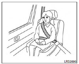
If you answered no to any of these questions, the child should remain in a booster seat using a three-point type seat belt.
NOTE:
Laws in some communities may follow different guidelines. Check local and state regulations to confirm your child is using the correct restraint system before traveling.
WARNING
Never let a child stand or kneel on any seat and do not allow a child in the cargo area.
The child could be seriously injured or killed in a sudden stop or collision.
 Children need adults to help protect them.
They need to be properly restrained.
In addition to the general information in this
manual, child safety information is available from
many other sources, including doctors, teachers,
government ...
 Child restraints
...
Other materials:
Normal operating condition
COMPASS
COMPASS : Description
COMPASS
The electronic compass is highly protected from
changes in most magnetic fields. However, some large
changes in magnetic fields can affect it. Some examples are (but not limited
to): high tension power lines,
large steel buildings, sub ...
Outside the vehicle
The maintenance items listed here should be
performed from time to time, unless otherwise
specified.
Doors and engine hood: Check that the doors
and engine hood operate properly. Also ensure
that all latches lock securely. Lubricate hinges,
latches, latch pins, rollers and links if necessary ...
Automatic drive positioner control unit
Reference Value
TERMINAL LAYOUT
PHYSICAL VALUES
...
Nissan Maxima Owners Manual
- Illustrated table of contents
- Safety-Seats, seat belts and supplemental restraint system
- Instruments and controls
- Pre-driving checks and adjustments
- Monitor, climate, audio, phone and voice recognition systems
- Starting and driving
- In case of emergency
- Appearance and care
- Do-it-yourself
- Maintenance and schedules
- Technical and consumer information
Nissan Maxima Service and Repair Manual

0.0053