
Nissan Maxima Service and Repair Manual: System description
LUBRICATION SYSTEM
Lubrication Circuit
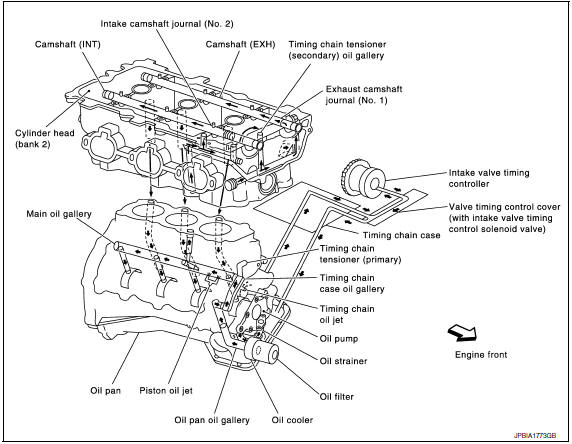
Schematic
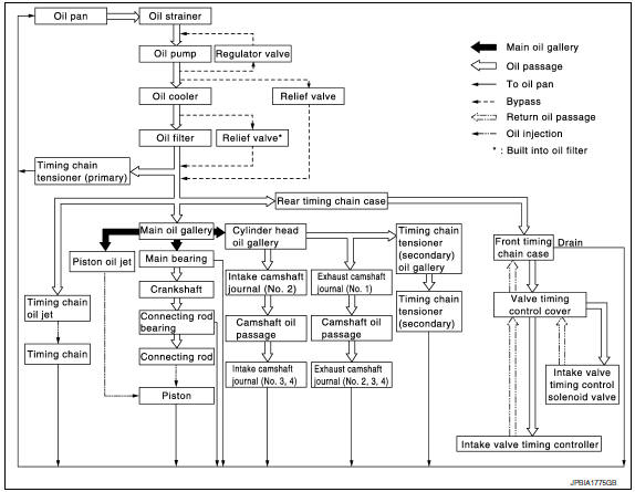
 Preparation
Special Service Tool
The actual shapes of the tools may differ from those illustrated here.
Commercial Service Tool
...

Other materials:
Preparation
PREPARATION
Special Service Tool
The actual shapes of the tools may differ from those illustrated here.
HFC-134a (R-134a) Service Tool and Equipment
Do not mix HFC-134a (R-134a) refrigerant and/or its specified oil with CFC-12
(R-12) refrigerant and/or its oil.
Separate and non-interchang ...
B257B, B257C ambient sensor
Description
COMPONENT DESCRIPTION
Ambient Sensor
The ambient sensor (1) is installed to the front bumper
reinforcement.
It detects ambient temperature and converts it into a resistance
value which is then input into the A/C auto amp.
Ambient Sensor Circuit
AMBIENT TEMPERATUR ...
P0441 evap control system
DTC Logic
DTC DETECTION LOGIC
NOTE:
If DTC P0441 is displayed with other DTC such as P2122, P2123, P2127, P2128 or
P2138, first perform
trouble diagnosis for other DTC.
In this evaporative emission (EVAP) control system, purge flow occurs during
non-closed throttle conditions.
Purge vo ...
Nissan Maxima Owners Manual
- Illustrated table of contents
- Safety-Seats, seat belts and supplemental restraint system
- Instruments and controls
- Pre-driving checks and adjustments
- Monitor, climate, audio, phone and voice recognition systems
- Starting and driving
- In case of emergency
- Appearance and care
- Do-it-yourself
- Maintenance and schedules
- Technical and consumer information
Nissan Maxima Service and Repair Manual

0.0232