Nissan Maxima Service and Repair Manual: Preparation
PREPARATION
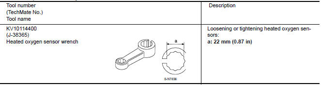
Special Service Tool
The actual shapes of the tools may differ from those illustrated here.
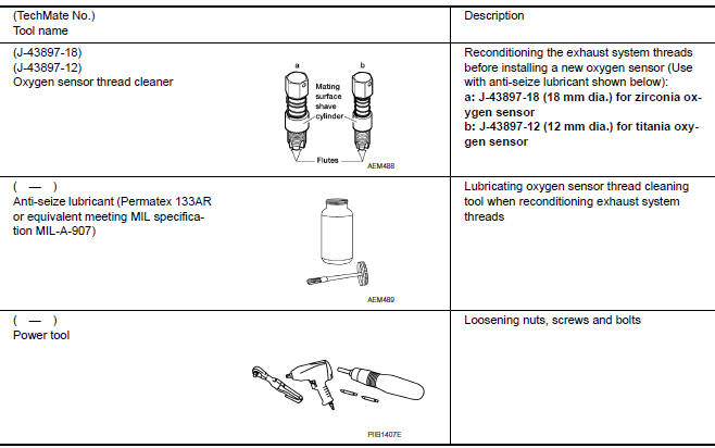
Commercial Service Tool
 Precaution
PRECAUTIONS
Precaution for Supplemental Restraint System (SRS) "AIR BAG" and
"SEAT BELT PRE-TENSIONER"
The Supplemental Restraint System such as "AIR BAG" and "SEAT BELT
PRE-TENSIONER", used alo ...
 Periodic maintenance
EXHAUST SYSTEM
Checking Exhaust System
Check the exhaust pipes, muffler, and mounting components for incorrect
attachment, leaks, cracks, damage, or deterioration. ...
Other materials:
Composite image signal circuit
Description
AV control unit transmits the playback DVD image signal and AUX image signal
to the display unit.
Diagnosis Procedure
1.CHECK CONTINUITY COMPOSITE IMAGE SIGNAL CIRCUIT
Turn ignition switch OFF.
Disconnect AV control unit connector M163 and display unit
connector
M142 ...
Opening the fuel-filler door
The fuel-filler door automatically unlocks when
the driver's door is unlocked.
1. Unlock the fuel-filler door using one of the
following operations.
Unlock the driver's door with the Intelligent
Key.
Push the power door lock switch to the
unlock position.
Push the door handle re ...
Door
FRONT DOOR
FRONT DOOR : Exploded View
Front door panel
Front door check link
Front door lower hinge
Front lower hinge
Grease
FRONT DOOR : Removal and Installation
CAUTION:
Use two people when removing or installing the front door
assembly due to its heavy weight. ...
Nissan Maxima Owners Manual
- Illustrated table of contents
- Safety-Seats, seat belts and supplemental restraint system
- Instruments and controls
- Pre-driving checks and adjustments
- Monitor, climate, audio, phone and voice recognition systems
- Starting and driving
- In case of emergency
- Appearance and care
- Do-it-yourself
- Maintenance and schedules
- Technical and consumer information
Nissan Maxima Service and Repair Manual

0.0072