Nissan Maxima Service and Repair Manual: Periodic maintenance
EXHAUST SYSTEM
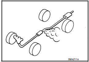
Checking Exhaust System

Check the exhaust pipes, muffler, and mounting components for incorrect attachment, leaks, cracks, damage, or deterioration.
 Preparation
PREPARATION
Special Service Tool
The actual shapes of the tools may differ from those illustrated here.
Commercial Service Tool
...
 Removal and installation
EXHAUST SYSTEM
Exploded View
Front exhaust tube
Ring gasket
Front exhaust tube stay
Front exhaust tube bracket
Gasket
Center exhaust tube rubber hanger
Center exhaust tube
Cent ...
Other materials:
P0139, P0159 HO2S2
Description
The heated oxygen sensor 2, after three way catalyst (manifold),
monitors the oxygen level in the exhaust gas on each bank.
Even if switching characteristics of the air fuel ratio (A/F) sensor 1
are shifted, the air-fuel ratio is controlled to stoichiometric, by the signal
...
Key slot
Diagnosis Procedure
Regarding Wiring Diagram information, refer to SEC-147,
"Wiring Diagram" or SEC-128, "Wiring Diagram".
1.CHECK KEY SLOT POWER SUPPLY CIRCUIT
Turn ignition switch OFF.
Disconnect key slot connector.
Check voltage between slot harness co ...
Parking brake system
On-Vehicle Service
PEDAL STROKE
When parking brake pedal is operated with the specified force,
make sure the stroke is within the specified
number of notches. Check by listening and counting the ratchet clicks.
Pedal stroke : Refer to PB-11, "Parking Brake Control".
INSPECTI ...
Nissan Maxima Owners Manual
- Illustrated table of contents
- Safety-Seats, seat belts and supplemental restraint system
- Instruments and controls
- Pre-driving checks and adjustments
- Monitor, climate, audio, phone and voice recognition systems
- Starting and driving
- In case of emergency
- Appearance and care
- Do-it-yourself
- Maintenance and schedules
- Technical and consumer information
Nissan Maxima Service and Repair Manual
0.0094
