Nissan Maxima Service and Repair Manual: CVT shift selector
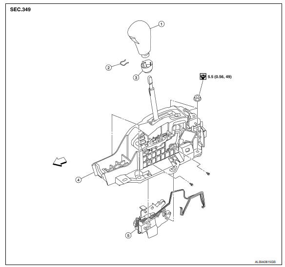
Exploded View
-
CVT shift selector handle
-
Shift selector handle clip
-
Shift selector handle cover
-
CVT shift selector assembly
-
Shift lock unit
 :Front
Removal and Installation
REMOVAL
-
Disconnect the battery negative terminal. Refer to PG-67, "Exploded View".
-
Move CVT shift selector to "N" position.
-
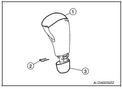
Slide shift selector handle cover (3) downward.
CAUTION: Be careful not to damage shift selector handle cover.
-
Pull shift selector handle clip (2) out of CVT shift selector handle (1).
-
Remove CVT shift selector handle and shift selector handle cover.
-
Remove center console assembly. Refer to IP-11, "Removal and Installation".
7. Move CVT shift selector to "P" position.
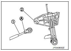
8. Remove control cable (1) from CVT shift selector assembly.
Refer to TM-173, "Exploded View".
9. Remove CVT shift selector assembly (2).
 :Nut
:Nut

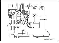
10. Disconnect CVT shift selector harness connector (A) using a suitable tool.
11. Remove shift lock unit from CVT shift selector assembly.
INSTALLATION
Installation is in the reverse order of removal.
-
When installing control cable (1) to CVT shift selector assembly (2), check that control cable is fully pressed in with the ribbed surface (A) facing upward.
Inspection and Adjustment
INSPECTION
-
Move CVT shift selector to "P" position, and turn ignition switch ON (engine stop).
-
Check that CVT shift selector can be moved from "P" position when brake pedal is depressed. Also check that CVT shift selector can be moved from "P" position only when brake pedal is depressed.
-
Move CVT shift selector and check for excessive effort, sticking, noise or rattle.
-
Check that CVT shift selector stops at each position with the feel of engagement when it is moved through all the positions. Check that the actual position of CVT shift selector matches the position shown by shift position indicator and manual lever on the transaxle.
-
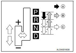
The method of operating CVT shift selector to individual positions correctly should be as shown.
-
(A): Press shift selector handle button to operate CVT shift selector, while depressing the brake pedal.
-
(B): Press shift selector handle button to operate CVT shift selector.
-
(C): CVT shift selector can be operated without pressing shift selector handle button.
-
-
When shift selector handle button is pressed in "P", "R", "N" or "D" position without applying forward/backward force to CVT shift selector, check shift selector handle button operation for sticking.
-
Check that back-up lamps illuminate only when CVT shift selector is placed in the "R" position.
-
Check that back-up lamps do not illuminate when CVT shift selector is pushed toward the "R" position when in the "P" or "N" position.
CAUTION: Check the lighting without pressing shift selector handle button.
-
Check that the engine can only be started with CVT shift selector in the "P" and "N" positions.
-
Check that transaxle is locked completely when CVT shift selector is in "P" position.
-
. Check the operation of manual mode.
-
When CVT shift selector is set to manual shift gate, make sure manual mode is displayed on combination meter.
-
Shift CVT shift selector to "+" and "-" sides, and make sure set shift position changes.
-
ADJUSTMENT
-
Set the park brake.
CAUTION: Make sure the vehicle cannot move with parking brake set.
-
Loosen the control cable nut and place the manual lever in "P" position.
-
Place the CVT shift selector in "P" position.
-
Push the control cable in with a load of 9.8 N (approximately 1 kg, 2.2 lb). Release the cable and temporarily tighten the control cable nut.
NOTE: Do not move the manual lever. Make sure the manual lever stays in the "P" position.
-
Tighten the control cable nut. Refer to TM-173, "Exploded View".
CAUTION: Secure manual lever when tightening nut.
-
Check the operation of the CVT.
 TCM
TCM
Exploded View
Bracket
TCM
Vehicle front
Removal and Installation
CAUTION:
Do not impact the TCM when removing
or installing TCM.
W ...
 Control cable
Exploded View
CVT shift selector assembly
Control cable
Retainer grommet
Lock plate
Bracket
Transaxle assembly
...
Other materials:
Windshield glass
Exploded View
Windshield glass
Spacer
Mirror base
Adhesive
Primer
Windshield molding
Metal roof
Dual Panel Sunroof
Front pillar
Cowl top
Rubber dam G.
16 mm (0.63 in) for top and sides 25 mm
(0.98 in) for bottom
12 + 2, - 0 mm (0.47 + 0.08 - 0 in)
&n ...
Supplemental air bag warning light
The supplemental air bag warning light,
displaying in the instrument panel,
monitors
the circuits for the air bag systems, pretensioner(
s) and all related wiring.
When the ignition switch is placed in the ON
position, the supplemental air bag warning light
illuminates for about 7 sec ...
IPDM-E branch line circuit
Diagnosis Procedure
1.CHECK CONNECTOR
Turn the ignition switch OFF.
Disconnect the battery cable from the negative terminal.
Check the terminals and connectors of the IPDM E/R for damage,
bend and loose connection (unit side
and connector side).
2.CHECK HARNESS FOR OPEN CIRCUIT
...
Nissan Maxima Owners Manual
- Illustrated table of contents
- Safety-Seats, seat belts and supplemental restraint system
- Instruments and controls
- Pre-driving checks and adjustments
- Monitor, climate, audio, phone and voice recognition systems
- Starting and driving
- In case of emergency
- Appearance and care
- Do-it-yourself
- Maintenance and schedules
- Technical and consumer information
Nissan Maxima Service and Repair Manual

0.0136