
Nissan Maxima Service and Repair Manual: Preparation
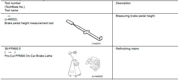
Special Service Tool
The actual shapes of the tools may differ from those illustrated here.
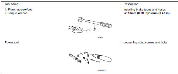
Commercial Service Tool
 Precaution
PRECAUTIONS
Precaution for Supplemental Restraint System (SRS) "AIR BAG" and "SEAT
BELT
PRE-TENSIONER"
The Supplemental Restraint System such as "AIR BAG" and "SEAT BELT
PR ...
 Symptom diagnosis
NOISE, VIBRATION AND HARSHNESS (NVH) TROUBLESHOOTING
NVH Troubleshooting Chart
Use the chart below to help you find the cause of the symptom. If necessary,
repair or replace these parts
&time ...
Other materials:
VDC
System Diagram
Hydraulic Circuit Diagram
Primary side
VDC/TCS/ABS actuator
Primary side VDC switch-over valve
1 (USV1)
Primary side VDC switch-over valve
1 (HSV1)
Primary side pump
Rear right inlet solenoid valve
Primary side inlet valve
Primary side damper
Fr ...
B2632, B2633 air mix door motor (driver side)
Description
COMPONENT DESCRIPTION
Air Mix Door Motor (Driver side)
The air mix door motor (driver side) (1) is attached to the heater
&
cooling unit assembly.
It rotates so that the air mix door is opened or closed to a
position
set by the A/C auto amp.
Motor rotation is then ...
Turn signal and hazard warning lamps
System Diagram
System Description
BCM (Body Control Module) controls turn signal lamp (RH and LH) and
hazard warning lamp operation
Combination meter operates turn signal indicator (RH and LH)
according to CAN communication signals from BCM.
Component Parts Location
BCM M16 ...
Nissan Maxima Owners Manual
- Illustrated table of contents
- Safety-Seats, seat belts and supplemental restraint system
- Instruments and controls
- Pre-driving checks and adjustments
- Monitor, climate, audio, phone and voice recognition systems
- Starting and driving
- In case of emergency
- Appearance and care
- Do-it-yourself
- Maintenance and schedules
- Technical and consumer information
Nissan Maxima Service and Repair Manual

0.0208