Nissan Maxima Service and Repair Manual: System description
REFRIGERATION SYSTEM
Refrigerant Cycle
Refrigerant flow
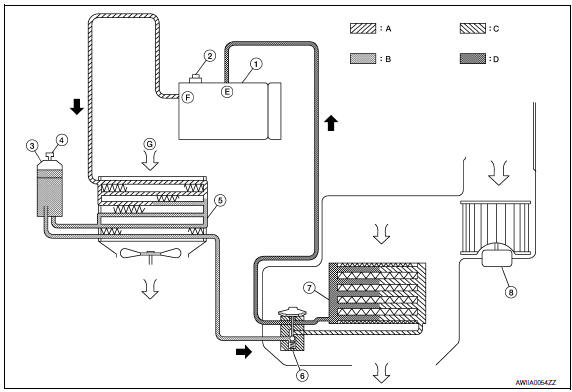
- Compressor
- Pressure relief valve
- Liquid tank
- Refrigerant pressure sensor
- Condenser
- Expansion valve
- Evaporator
- Blower motor
- High-pressure gas
- High-pressure liquid
- Low-pressure liquid
- Low-pressure gas
- Suction port
- Discharge port
- Outside air
The refrigerant from the compressor flows through the condenser with liquid tank, the evaporator and returns to the compressor. The refrigerant evaporation in the evaporator is controlled by an expansion valve.
Component Part Location
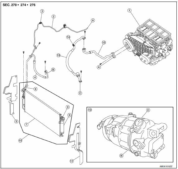
- Heater and cooling unit assembly
- High-pressure pipe
- High-pressure A/C service valve
- High-pressure flexible hose
- Air deflector (RH)
- Junction pipe
- Condenser
- Liquid tank
- Refrigerant pressure sensor
- Condenser, liquid tank and refrigerant pressure sensor
- Air deflector (LH)
- Compressor
- Low-pressure flexible hose
- Low-pressure A/C service valve
- Low-pressure pipe
- High-pressure pipe to heater and cooling unit assembly
- . High-pressure flexible hose to compressor
- Low-pressure flexible hose to compressor
Refrigerant System Protection
Refrigerant pressure sensor
The refrigerant system is protected against excessively high or low pressures by the refrigerant pressure sensor, located on the condenser. If the system pressure rises above or falls below the specifications, the refrigerant pressure sensor detects the pressure inside the refrigerant line and sends the voltage signal to the ECM.
The ECM then ceases to supply power to the A/C relay which disengages and stops the compressor when pressure on the high pressure side (as detected by refrigerant pressure sensor) is over approximately 2,746 kPa (28 kg/cm2, 398 psi), or below approximately 120 kPa (1.22 kg/cm2, 17.4 psi).
Pressure Relief Valve
The refrigerant system is also protected by a pressure relief valve, located in the rear head of the compressor.
When the pressure of refrigerant in the system increases to an abnormal level [more than 3,727 kPa (38 kg/ cm2, 540 psi)], the release port on the pressure relief valve automatically opens and releases refrigerant into the atmosphere.
 Preparation
PREPARATION
Special Service Tool
The actual shapes of the tools may differ from those illustrated here.
HFC-134a (R-134a) Service Tool and Equipment
Do not mix HFC-134a (R-134a) refrigerant an ...
 Basic inspection
DIAGNOSIS AND REPAIR WORK FLOW
WITH COLOR DISPLAY
WITH COLOR DISPLAY : How to Perform Trouble Diagnosis For Quick And
Accurate Repair
WORK FLOW
1.LISTEN TO CUSTOMER COMPLAINT
Interview the cust ...
Other materials:
Bluetooth control unit
Removal and Installation
REMOVAL
Disconnect the battery negative terminal. Refer to PG-67, "Removal
and Installation (Battery)".
Remove the trunk upper finisher. Refer to INT-23, "Exploded View".
Remove the parcel shelf finisher. Refer to INT-28, "Removal and
Installation".
From i ...
Wheel sensors
Exploded View - Front Wheel Sensor
Front wheel sensor
Color line (slant line)
Front wheel sensor harness connector
Front
Removal and Installation - Front Wheel Sensor
CAUTION:
Be careful not to damage wheel sensor edge and sensor rotor
teeth.
When pul ...
Roof link assembly
Removal and Installation
Removal
Remove the sunshade. Refer to RF-153, "Removal and Installation".
Remove the wind deflector. Refer to RF-168, "Removal and Installation".
Remove the glass lid assembly. Refer to RF-150, "Removal and
Installation".
Remove the sunroof motor. Refer to RF-1 ...
Nissan Maxima Owners Manual
- Illustrated table of contents
- Safety-Seats, seat belts and supplemental restraint system
- Instruments and controls
- Pre-driving checks and adjustments
- Monitor, climate, audio, phone and voice recognition systems
- Starting and driving
- In case of emergency
- Appearance and care
- Do-it-yourself
- Maintenance and schedules
- Technical and consumer information
Nissan Maxima Service and Repair Manual

0.0049