Nissan Maxima Service and Repair Manual: Preparation
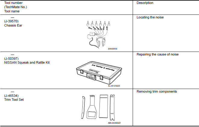
Special Service Tool
The actual shapes of the tools may differ from those illustrated here.
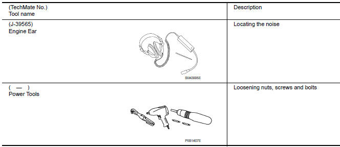
Commercial Service Tools
 Preparation
...
 Clip list
Descriptions for Clips
Replace any clips which are damaged during removal or installation
...
Other materials:
P1611 ID discord, IMMU-ECM
Description
BCM performs the ID verification with ECM that allows the
engine to start. Start the engine if the ID is OK.
ECM prevents the engine from starting if the ID is not registered. BCM starts
the communication with ECM if
ignition switch is turned ON.
DTC Logic
DTC DETECTION LOGIC ...
B1086 - B1089 seat belt pre-tensioner LH
Description
DTC B1086 - B1089 SEAT BELT PRE-TENSIONER LH
The seat belt pre-tensioner LH is wired to the air bag diagnosis sensor unit.
The air bag diagnosis sensor unitwill monitor for opens and shorts in
detected lines to the seat belt pre-tensioner LH.
PART LOCATION
DTC Logic
DTC DETECTIO ...
System description
CAN COMMUNICATION SYSTEM
CAN System Specification Chart
Determine CAN system type from the following specification chart.
NOTE:
Refer to LAN-15, "Trouble Diagnosis Procedure" for how to use CAN
system specification chart.
VEHICLE EQUIPMENT IDENTIFICATION INFORMATION
NOTE:
Check CAN system ...
Nissan Maxima Owners Manual
- Illustrated table of contents
- Safety-Seats, seat belts and supplemental restraint system
- Instruments and controls
- Pre-driving checks and adjustments
- Monitor, climate, audio, phone and voice recognition systems
- Starting and driving
- In case of emergency
- Appearance and care
- Do-it-yourself
- Maintenance and schedules
- Technical and consumer information
Nissan Maxima Service and Repair Manual

0.0068