Nissan Maxima Service and Repair Manual: Front seat
Exploded View
DRIVER
Driver Seat - Without Climate Controlled Seats
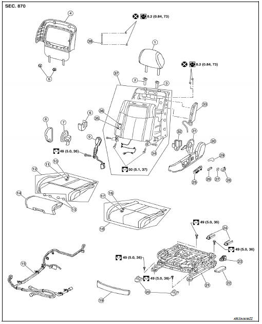
- Headrest
- Headrest holder (free)
- Headrest holder (locked)
- Seatback board
- Seatback board clip
- Seat cushion inner finisher inside (RH)
- Recline mechanism inner cover
- Seat cushion outer finisher (RH)
- Seat belt buckle
- Seat cushion trim
- Seat cushion pad
- Seat cushion assembly
- Thigh extension tether
- Thigh extension assembly
- Seat harness
- Seat cushion trim (w/o thigh extension)
- Seat cushion pad (w/o thigh extension)
- Seat cushion assembly (w/o thigh extension)
- Seat cushion front finisher
- Front slide cover
- Seat frame assembly
- Power seat control unit
- Actuator bracket
- Rear slide cover
- Power seat switch
- Seat slide and lifter switch knob
- Seat recline knob
- Lumbar support switch (if equipped)
- Lumbar lever (if equipped)
- Seat cushion outer finisher (LH)
- Recline device outer cover
- Seat cushion inner finisher (LH)
- Side air bag module
- Seatback frame
- Seatback pad
- Seatback trim
- Seatback assembly
- Chute rod
PASSENGER
Passenger Seat
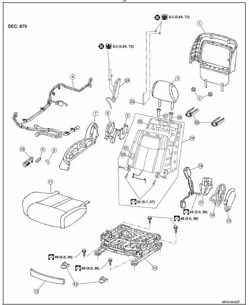
- Seatback board
- Seatback board clip
- Headrest
- Seat harness
- Seat cushion inner finisher inside (RH)
- Recline device inner cover
- Seat cushion outer finisher (RH)
- Seat recline knob
- Seat slide and lifter switch knob
- Power seat switch
- Seat cushion assembly
- Seat cushion front finisher
- Front slide cover
- Seat frame assembly
- Seat cushion outer finisher (LH)
- Recline mechanism inner cover
- Seat cushion inner finisher inside (LH)
- Seat belt buckle
- Seatback assembly
- Seatback pad
- Seatback trim
- Seatback frame
- Chute rod
- Side air bag module
- Rear slide cover
- Headrest holder (locked)
- Headrest holder (free)
Removal and Installation
REMOVAL
WARNING:
Do not leave any objects (screwdrivers, tools, etc.) on the seat during seat repair. It can lead to personal injury if the side air bag module should accidentally deploy.
CAUTION:
- When removing or installing the seat trim, handle it carefully to keep dirt out and to avoid damage.
- When checking the power seat circuit for continuity using a circuit tester, do not confuse its connector with the side air bag module connector. Such an error may cause the air bag module to deploy.
- Do not drop, tilt, or bump the side air bag module while installing the seat. Always handle it with care.
- After the front side air bag module inflates, the front seatback assembly must be replaced.
- When removing and installing the seat, use shop cloths to protect components from damage.
- Before removing the front seat, turn the ignition switch OFF, disconnect both battery terminals and wait at least three minutes.
- Slide the seat to the full froward position.
- Remove the rear slide covers. a. Release the pawls (A).
b. Remove the rear slide covers.
3. Remove the rear mount bolts.
4. Slide the seat to the full rearward position.
5. Remove the front slide covers.
6. Remove the front mount bolts.
7. Disconnect the negative and positive battery terminals and wait at least three minutes. Refer to PG-67, "Removal and Installation (Battery)".
8. Disconnect the harness connector under the seat and remove harness clips.
9. Remove seat from the vehicle.
INSTALLATION
Installation is in the reverse order of removal.
CAUTION:
Make sure that the seat harness or the floor trim is not damaged during installation.
NOTE:
- When installing the LH front seat, tighten the bolts in the order shown.
- When installing the RH front seat, tighten the bolts in the order shown.

 Rear seat
Exploded View - Fixed Seatback
Headrest
Headrest holder (free)
Headrest holder (locked)
Bumper
Seatback assembly
Seatback trim
Seatback pad
Seat cushion trim
Seat cushion p ...
Other materials:
Sunshade motor assembly
Wiring Diagram
...
Blower motor
Description
COMPONENT DESCRIPTION
Brush-less Motor
The blower motor utilizes a brush-less motor with a rotating magnet.
Quietness is improved over previous motors where the brush was
the point of contact and the coil rotated.
Blower Motor Circuit
Component Function Check
1.CHECK OP ...
Air Cleaner And Air Duct
Removal and Installation
Air duct hose and resonator assembly
Front air duct
Air cleaner case (lower)
Grommets
Air cleaner case mounting bracket
Bracket
Air cleaner filter
Air cleaner case (upper)
Mass air flow sensor
To electric throttle control
actuator
...
Nissan Maxima Owners Manual
- Illustrated table of contents
- Safety-Seats, seat belts and supplemental restraint system
- Instruments and controls
- Pre-driving checks and adjustments
- Monitor, climate, audio, phone and voice recognition systems
- Starting and driving
- In case of emergency
- Appearance and care
- Do-it-yourself
- Maintenance and schedules
- Technical and consumer information
Nissan Maxima Service and Repair Manual

0.0073