Nissan Maxima Service and Repair Manual: Rear seat
Exploded View - Fixed Seatback
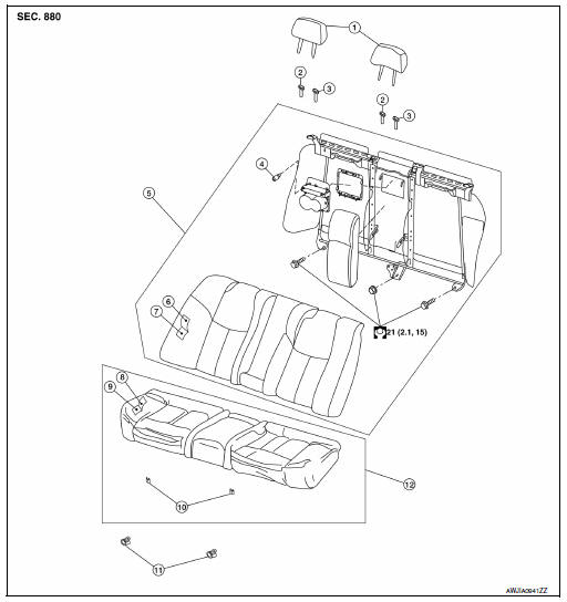
- Headrest
- Headrest holder (free)
- Headrest holder (locked)
- Bumper
- Seatback assembly
- Seatback trim
- Seatback pad
- Seat cushion trim
- Seat cushion pad
- Seat cushion wire cover
- Seat cushion lock
- Seat cushion assembly
Removal and Installation
CAUTION:
When removing and installing, use shop cloths to protect parts from damage.
SEAT CUSHION ASSEMBLY
Removal
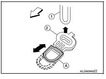
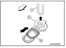
- Locate the seat cushion lock (2) at the front bottom of the seat
cushion assembly (one for each side). Pull the release lever (A)
forward and lift the seat cushion assembly upward to release the
seat cushion wire (1) from the seat cushion lock (2).
 : Front
 - Then pull the seat cushion assembly forward to remove.
Installation is in the reverse order of removal.
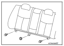
SEATBACK
Removal
- Remove the seat cushion assembly.
- Remove the headrests (LH/RH).
- Remove the seatback frame bolts and nut.
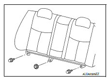
4. Lift the seatback to disengage seat hook wires from the hangers.
Installation
Installation is in the reverse order of removal.
Exploded View - 60:40 Split Seatback
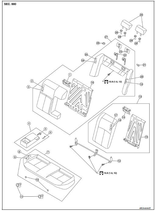
- Seatback latch striker (RH)
- Seatback trim (RH)
- Seatback pad (RH)
- Armrest assembly
- Inner armrest bracket (RH)
- Inner armrest bracket (LH)
- Seat cushion assembly
- Seat cushion trim
- Seat cushion pad
- Seat cushion wire cover
- Seat cushion lock
- Seatback hinge assembly
- Seatback assembly (LH)
- Seatback latch striker (LH)
- Seatback frame (LH)
- Seatback pad (LH)
- Seatback trim (LH)
- Seatback frame (RH)
- Side bolster pad (LH)
- Side bolster trim (LH)
- Seat belt guide (LH)
- Seatback latch assembly
- Seatback latch cover
- Side bolster pad (RH)
- Side bolster trim (RH)
- Seat belt guide (RH)
- Seatback assembly (RH)
- Headrest holder (locked)
- Headrest holder (free)
- Headrest
Removal and Installation
CAUTION:
When removing and installing, use shop cloths to protect parts from damage.
SEAT CUSHION ASSEMBLY
Removal
- Locate the seat cushion lock (2) at the front bottom of the seat
cushion assembly (one for each side). Pull the release lever (A)
forward and lift the seat cushion assembly upward to release the
seat cushion wire (1) from the seat cushion lock (2).
 : Front
 - Then pull the seat cushion assembly forward to remove.
Installation
Installation is in the reverse order of removal.
SEATBACK
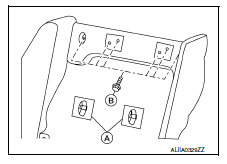
Removal
- Lock seatback (LH/RH) in upright position.
- Remove the seatback hinge assembly bolts and nut.
- Fold seatback (LH/RH) forward.
4. Remove seatback latch covers (A).
5. Remove the halo upper frame assembly bolts (B).
6. Remove the seatback assembly.
Installation
Installation is in the reverse order of removal.
 Front seat
Exploded View
DRIVER
Driver Seat - Without Climate Controlled Seats
Headrest
Headrest holder (free)
Headrest holder (locked)
Seatback board
Seatback board clip
Seat cushion inner ...

Other materials:
Satellite radio tuner
Reference Value
PHYSICAL VALUES
...
Power window and door lock/unlock switch RH
Reference Value
TERMINAL LAYOUT
PHYSICAL VALUES
POWER WINDOW AND DOOR LOCK/UNLOCK SWITCH RH
Fail Safe
FAIL-SAFE CONTROL
Switches to fail-safe control when malfunction is detected in encoder signal
that detects up/down speed and
direction of door glass. Switches to fail-safe con ...
B1150 - B1153 side curtain air bag module LH
Description
DTC B1150 - B1153 LH SIDE CURTAIN AIR BAG MODULE
The LH side curtain air bag module is wired to the air bag diagnosis sensor
unit. The air bag diagnosis sensorunit will monitor for opens and shorts in
detected lines to the LH side curtain air bag module.
PART LOCATION
DTC Logic
...
Nissan Maxima Owners Manual
- Illustrated table of contents
- Safety-Seats, seat belts and supplemental restraint system
- Instruments and controls
- Pre-driving checks and adjustments
- Monitor, climate, audio, phone and voice recognition systems
- Starting and driving
- In case of emergency
- Appearance and care
- Do-it-yourself
- Maintenance and schedules
- Technical and consumer information
Nissan Maxima Service and Repair Manual

0.0067