Nissan Maxima Service and Repair Manual: Preparation
PREPARATION
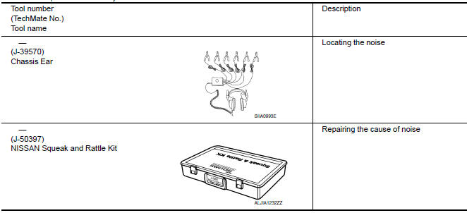
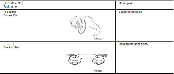
Special Service Tools
The actual shapes of the tools may differ from those illustrated here.
Commercial Service Tools
 Precaution
PRECAUTIONS
Precaution for Supplemental Restraint System (SRS) "AIR BAG" and
"SEAT BELT PRE-TENSIONER"
The Supplemental Restraint System such as "AIR BAG" and "SEAT BELT
PRE-TENSIONER", used alo ...
 Symptom diagnosis
SQUEAK AND RATTLE TROUBLE DIAGNOSES
Work Flow
CUSTOMER INTERVIEW
Interview the customer if possible, to determine the conditions that exist
when the noise occurs. Use the Diagnostic Worksheet ...
Other materials:
ECU diagnosis information
A/C AUTO AMP.
Reference Value
VALUES ON THE DIAGNOSIS TOOL
CONSULT MONITOR ITEM
A/C AUTO AMP. HARNESS CONNECTOR TERMINAL LAYOUT
TERMINALS AND REFERENCE VALUES FOR A/C AUTO AMP.
DTC Inspection Priority Chart
If some DTCs are displayed at the same time, perform inspections one b ...
Parking/parking on hills
WARNING
Do not stop or park the vehicle over
flammable materials such as dry grass,
waste paper or rags. They may ignite
and cause a fire.
Safe parking procedures require that
both the parking brake be set and the
transmission placed into P (Park). Failure
to do so could cause ...
Precaution
PRECAUTIONS
Precaution for Supplemental Restraint System (SRS) "AIR BAG" and
"SEAT BELT PRE-TENSIONER
The Supplemental Restraint System such as "AIR BAG" and "SEAT BELT
PRE-TENSIONER", used along with a front seat belt, helps to reduce the risk
or severity of injury to the driver and front p ...
Nissan Maxima Owners Manual
- Illustrated table of contents
- Safety-Seats, seat belts and supplemental restraint system
- Instruments and controls
- Pre-driving checks and adjustments
- Monitor, climate, audio, phone and voice recognition systems
- Starting and driving
- In case of emergency
- Appearance and care
- Do-it-yourself
- Maintenance and schedules
- Technical and consumer information
Nissan Maxima Service and Repair Manual

0.0059