Nissan Maxima Service and Repair Manual: Power supply and ground circuit
BCM
BCM : Diagnosis Procedure
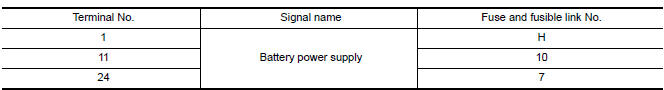
1. CHECK FUSE AND FUSIBLE LINK
Check if the following BCM fuses or fusible link are blown.
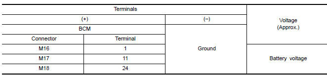
2. CHECK POWER SUPPLY CIRCUIT
- Turn ignition switch OFF.
- Disconnect BCM.
- Check voltage between BCM harness connector and ground.
3. CHECK GROUND CIRCUIT
Check continuity between BCM harness connector and ground.

BCM : Special Repair Requirement
1. REQUIRED WORK WHEN REPLACING BCM
Initialize control unit.
POWER WINDOW MAIN SWITCH
POWER WINDOW MAIN SWITCH : Diagnosis Procedure
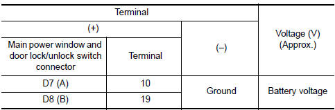
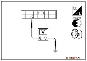
1. CHECK POWER SUPPLY CIRCUIT
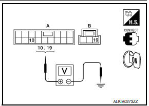
- Turn ignition switch ON.
- Check voltage between main power window and door lock/ unlock switch connectors D7 (A) terminal 10 and D8 (B) terminal 19 and ground.
2. CHECK HARNESS CONTINUITY
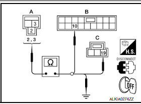
- Turn ignition switch OFF.
- Disconnect BCM connector M16 and main power window and door lock/unlock switch connectors.
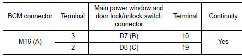
- Check continuity between BCM connector M16 (A) terminals 2 and 3 and main power window and door lock/unlock switch connectors D7 (B) terminal 10 and D8 (C) terminal 19.
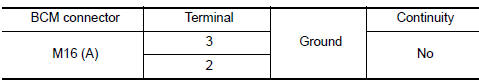
- Check continuity between BCM connector M16 (A) terminals 2 and 3 and ground.
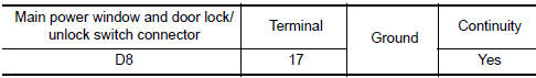
3. CHECK GROUND CIRCUIT
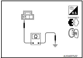
- Turn ignition switch OFF.
- Disconnect main power window and door lock/unlock switch connector D8.
- Check continuity between main power window and door lock/ unlock switch connector D8 terminal 17 and ground.
POWER WINDOW MAIN SWITCH : Special Repair Requirement
1. PERFORM INITIALIZATION PROCEDURE
Perform initialization procedure.
2. CHECK ANTI-PINCH OPERATION
Check anti-pinch operation.
FRONT POWER WINDOW SWITCH
FRONT POWER WINDOW SWITCH : Diagnosis Procedure
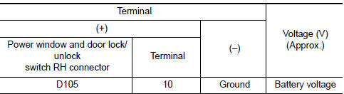
1. CHECK POWER SUPPLY CIRCUIT
Check voltage between power window and door lock/unlock switch RH connector D105 terminal 10 and ground
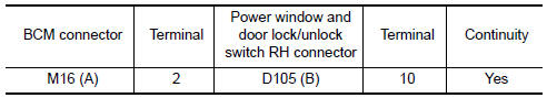
2. CHECK HARNESS CONTINUITY
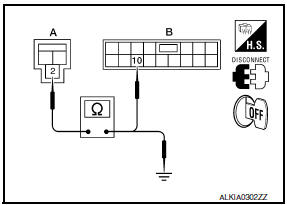
- Turn ignition switch OFF.
- Disconnect BCM connector M16 and power window and door lock/unlock switch RH connector.
- Check continuity between BCM connector M16 (A) terminal 2 and power window and door lock/unlock switch RH connector D105 (B) terminal 10.
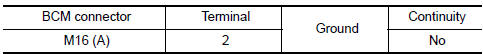
- Check continuity between BCM connector M16 (A) terminal 2 and ground.
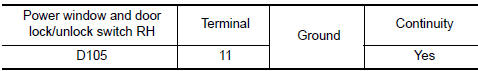
3. CHECK GROUND CIRCUIT
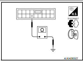
- Turn ignition switch OFF.
- Disconnect power window and door lock/unlock switch RH.
- Check continuity between power window and door lock/unlock switch RH connector D105 terminal 11 and ground.
FRONT POWER WINDOW SWITCH : Special Repair Requirement
1. PERFORM INITIALIZATION PROCEDURE
Perform initialization procedure.
2. CHECK ANTI-PINCH OPERATION
Check anti-pinch operation
REAR POWER WINDOW SWITCH
REAR POWER WINDOW SWITCH : Diagnosis Procedure
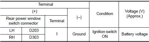
1. CHECK POWER SUPPLY CIRCUIT
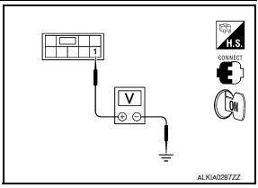
Check voltage between rear power window switch connector terminal 1 and ground.
2. CHECK HARNESS CONTINUITY
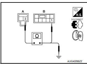
- Turn ignition switch OFF.
- Disconnect BCM connector M16 and rear power window switch connector.
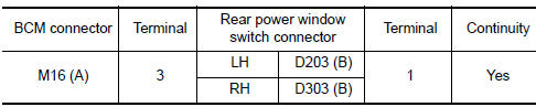
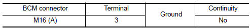
- Check continuity between BCM connector M16 (A) terminal 3 and rear power window switch connector (B) terminal 1.
- Check continuity between BCM connector M16 (A) terminal 3 and ground.
3. CHECK GROUND CIRCUIT
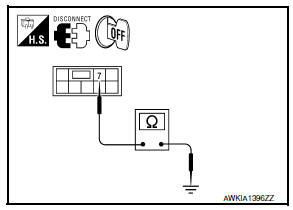
- Turn ignition switch OFF.
- Disconnect rear power window switch connector.
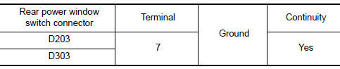
- Check continuity between rear power window switch connector terminal 7 and ground.
REAR POWER WINDOW SWITCH : Special Repair Requirement
1. PERFORM INITIALIZATION PROCEDURE
Perform initialization procedure
2. CHECK ANTI-PINCH OPERATION
Check anti-pinch operation

 Rear power window switch
Description
BCM supplies power.
Rear power window motor operates when rear power window switch is
activated.
Component Function Check
Rear Power Window Switch
1. CHECK REAR POWER WINDOW ...
Other materials:
Rear Timing Chain Case
Exploded View
Rear timing chain case
O-ring
Cylinder block
Removal and Installtion
CAUTION:
After removing timing chain, do not turn the crankshaft and
camshaft separately, or the valves will strike the pistons.
Before removing the upper oil pan, remove the crankshaft
posi ...
Rear door speaker
Description
The AV control unit sends audio signals to the rear door speakers using the
rear door speaker circuits.
Diagnosis Procedure
1.CONNECTOR CHECK
Check the AV control unit and speaker connectors for the following:
Proper connection
Damage
Disconnected or loose terminals
2.HA ...
Head restraints/headrests
WARNING
Head restraints/headrests supplement
the other vehicle safety systems. They may
provide additional protection against injury
in certain rear end collisions. Adjustable
head restraints/headrests must be
adjusted properly, as specified in this section.
Check the adjustment after someo ...
Nissan Maxima Owners Manual
- Illustrated table of contents
- Safety-Seats, seat belts and supplemental restraint system
- Instruments and controls
- Pre-driving checks and adjustments
- Monitor, climate, audio, phone and voice recognition systems
- Starting and driving
- In case of emergency
- Appearance and care
- Do-it-yourself
- Maintenance and schedules
- Technical and consumer information
Nissan Maxima Service and Repair Manual

0.0071