
Nissan Maxima Service and Repair Manual: Sunshade motor assembly
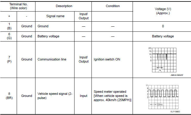
Reference Value
TERMINAL LAYOUT

PHYSICAL VALUES
 Sunroof motor assembly
Reference Value
TERMINAL LAYOUT
PHYSICAL VALUES
...
 Wiring diagram
...
Other materials:
Precautions on cruise control
1. CANCEL switch
2. RES+ switch
3. SET- switch
4. ON/OFF cruise switch
If the cruise control system malfunctions, it
cancels automatically.
WARNING
Do not use the cruise control when driving
under the following conditions:
When it is not possible to keep the
vehicle at ...
RGB (G: green) signal circuit
Description
Transmit the image displayed with AV control unit with RGB signal to the
display unit.
Diagnosis Procedure
1.CHECK CONTINUITY RGB (G: GREEN) SIGNAL CIRCUIT
Turn ignition switch OFF.
Disconnect display unit connector M141 and AV control unit
connector M117.
Check conti ...
Front tweeter
Removal and Installation
REMOVAL
Remove the front pillar finisher. Refer to INT-24, "Removal and
Installation".
Remove the front tweeter speaker grille. Refer to IP-10, "Exploded
View".
Remove the front tweeter speaker screws (A).
Pull out front tweeter speaker (1), disconnect the ...
Nissan Maxima Owners Manual
- Illustrated table of contents
- Safety-Seats, seat belts and supplemental restraint system
- Instruments and controls
- Pre-driving checks and adjustments
- Monitor, climate, audio, phone and voice recognition systems
- Starting and driving
- In case of emergency
- Appearance and care
- Do-it-yourself
- Maintenance and schedules
- Technical and consumer information
Nissan Maxima Service and Repair Manual

0.0129