Nissan Maxima Service and Repair Manual: Sunroof motor assembly
Wiring Diagram
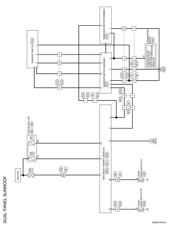
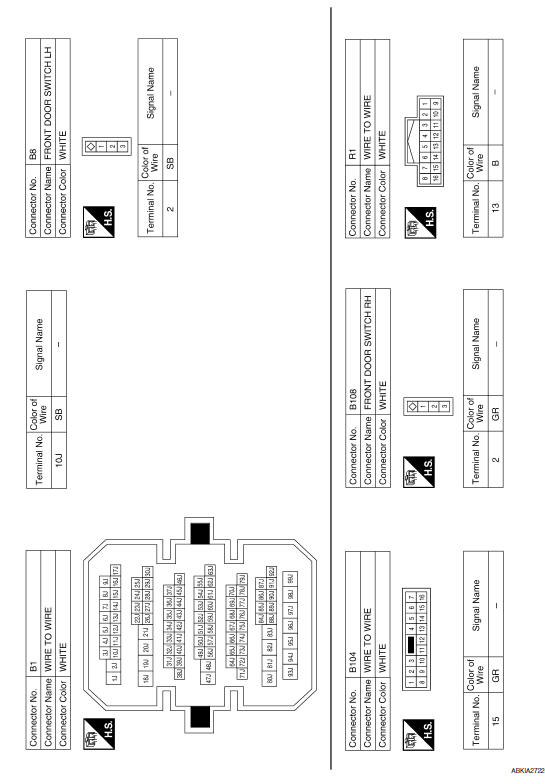
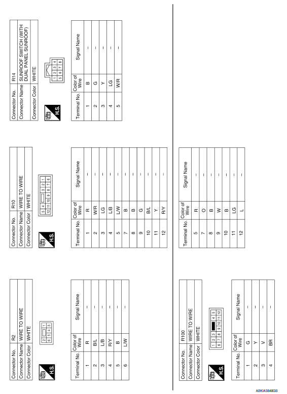
 Wiring diagram
...
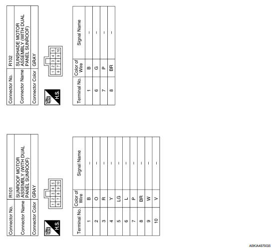
 Sunshade motor assembly
Wiring Diagram
...
Other materials:
B2556 push-button ignition switch
Description
The switch that changes the power supply position. BCM
maintains the power supply position status. BCM
changes the power supply position with the operation of the push-button ignition
switch.
DTC Logic
DTC DETECTION LOGIC
DTC CONFIRMATION PROCEDURE
1.PERFORM DTC CONFIRMATION ...
Compressor control function
Description
PRINCIPLE OF OPERATION
A/C compressor is not activated.
Functional circuit diagram
CAN (1): A/C switch signal
: Blower fan motor switch signal
CAN (2): A/C compressor request signal
RX: A/C switch signal
: Fan ON signal
: Defroster signal
Functional initial inspection chart ...
Inspection and adjustment
ECM RE-COMMUNICATING FUNCTION
ECM RE-COMMUNICATING FUNCTION : Description
the ECM has been replaced with a new one (*1).
*1: New one means an ECM which has never been energized on-board.
(In this step, initialization procedure by CONSULT is not necessary)
NOTE:
When registering new Key ...
Nissan Maxima Owners Manual
- Illustrated table of contents
- Safety-Seats, seat belts and supplemental restraint system
- Instruments and controls
- Pre-driving checks and adjustments
- Monitor, climate, audio, phone and voice recognition systems
- Starting and driving
- In case of emergency
- Appearance and care
- Do-it-yourself
- Maintenance and schedules
- Technical and consumer information
Nissan Maxima Service and Repair Manual

0.0076