Nissan Maxima Service and Repair Manual: Roof finisher
Removal and Installation
REMOVAL
- Open the glass lid.
- Apply protective tape around the roof side finisher to protect the surface from damage.
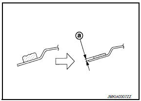
- Cut adhesive.
- Pass piano wire through the adhesive with a wire pierce.
- Tie piano wire on both ends to assist in wire grip.
- Pull piano wire with sawing motion to cut through adhesive, working along the length of the panel.
- Remove the roof side finisher.
INSTALLATION
WARNING:
- Keep heat and open flames away as primers and adhesive are flammable.
- The materials contained in the kit are harmful if swallowed, and may irritate skin and eyes. Never let them contact the skin or eyes.
- Use in an open, well ventilated location. Never breathe the
vapors. They may be harmful if inhaled.
Move immediately to an area with fresh air if affected by vapor inhalation.
NOTE:
- Use a genuine Nissan Urethane Adhesive Kit (if available) or an equivalent and follow the instructions furnished with it.
- Inform the customer that the vehicle should remain stationary until the urethane adhesive has completely cured (approximately 24 hours). Curing time varies with temperature and humidity.
- Using a knife or spatula, trim the adhesive (sealant) remaining on body down to approximately 2 mm thick (a) so that the contour becomes smooth.
CAUTION: If bonded area on body is scratched, be sure to repair it with a 2-component urethane. Do not use lacquer.
- When installing new roof side finisher, position the roof side finisher dry (no adhesive) first onto the vehicle and paint mating marks on the body and roof side finisher, then remove it again.
- Thoroughly clean bonding area on the roof side finisher and the body with isopropyl alcohol or equivalent.
- Apply primer to the body and the roof side trim (lower) surfaces.
- Apply adhesive to the contact areas of the body within the time specified in the instructions for the adhesive.
- Open adhesive by cutting off the nozzle tip and set it in a sealant gun.
- Form a continuous bead of adhesive resembling the measurements in applied thickness (A), and in applied width (B) on the body panel.
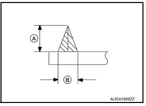
Adhesive applied thickness (A) : 13 +- 1 mm (0.51 +- 0.039 in)
Adhesive
applied width (B) : 8 +- 1 mm (0.31 +- 0.039 in)
- Position the roof side finisher, align the paint marks, then lower it into position.
- Press down lightly by hand to evenly expand the adhesive contact with the roof side finisher.
- Using a suitable tool, remove any adhesive overflow.
- Remove the protective tape.
 Sunroof unit assembly
Inspection and Adjustment
INSPECTION
Wind Deflector
Open glass lid assembly fully.
Visually check for proper installation, damaged/deteriorated
components, or foreign objects within mec ...
 Front sunroof glass
Removal and Installation
REMOVAL
Remove the wind deflector. Refer to RF-168, "Removal and
Installation".
Tape down the glass lid weatherstrip along the from sunroof glass
with protective ...
Other materials:
B1081 - B1084 seat belt pre-tensioner RH
Description
DTC B1081 - B1084 SEAT BELT PRE-TENSIONER RH
The seat belt pre-tensioner RH is wired to the air bag diagnosis sensor unit.
The air bag diagnosis sensor unitwill monitor for opens and shorts in
detected lines to the seat belt pre-tensioner RH.
PART LOCATION
DTC Logic
DTC DETECTIO ...
U1010 control unit (CAN)
Description
Refer to LAN-24, "CAN Communication Signal Chart".
DTC Logic
DTC DETECTION LOGIC
DTC No.
Trouble diagnosis name
DTC detecting condition
Possible cause
U1010
CONTROL UNIT (CAN
When detecting error during the initial diagnosis of CAN controller
of dri ...
Engine coolant temperature gauge
The gauge indicates the engine coolant temperature.
The engine coolant temperature is within the
normal range 1 when the gauge needle points
within the zone shown in the illustration.
The engine coolant temperature varies with the
outside air temperature and driving conditions.
CAUTION ...
Nissan Maxima Owners Manual
- Illustrated table of contents
- Safety-Seats, seat belts and supplemental restraint system
- Instruments and controls
- Pre-driving checks and adjustments
- Monitor, climate, audio, phone and voice recognition systems
- Starting and driving
- In case of emergency
- Appearance and care
- Do-it-yourself
- Maintenance and schedules
- Technical and consumer information
Nissan Maxima Service and Repair Manual

0.0066