Nissan Maxima Service and Repair Manual: Headlamp aiming adjustment
Description
PREPARATION BEFORE ADJUSTING
CAUTION: Do not use organic solvent (thinner, gasoline etc.).
NOTE:
- For details, refer to the regulations in your own country.
- Perform aiming adjustment if the vehicle front body has been repaired and/or the headlamp assembly has been replaced.
Before performing aiming adjustment, check the following.
- Keep all tires inflated to correct pressure.
- Place vehicle on level ground.
- See that the vehicle is unloaded (except for full levels of coolant, engine oil and fuel, and spare tire, jack, and tools). Have the driver or equivalent weight placed in drivers seat.
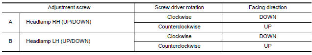
AIMING ADJUSTMENT SCREW
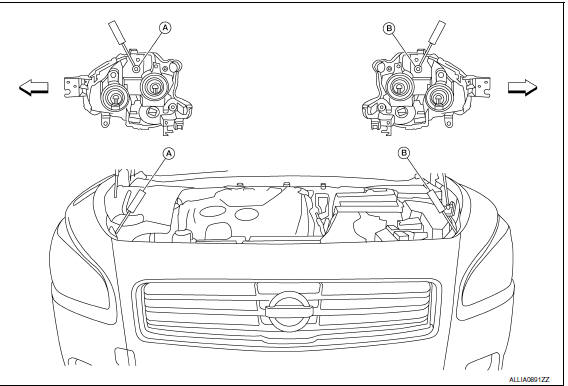
- Headlamp RH (UP/DOWN) adjustment screw
- Headlamp LH (UP/DOWN) adjustment screw
 Vehicle center
Aiming Adjustment Procedure
NOTE: Set the screen so that it is perpendicular to the road.
- Position the screen.
- Make the distance between the headlamp center and the screen 7.62 m (25 ft).
- Start the engine and illuminate the headlamp (LO).
CAUTION: Do not cover the lens surface with tape, etc. The lens is made of plastic.
NOTE: Block the light from the headlamp that is not being adjusted with a thick fabric or similar object, so that it does not reach the screen.
- Use the adjustment screw to adjust the low beams on the screen, so that it is within the aiming adjustment area.
Adjustment Using An Adjustment Screen (Light/Dark Borderline)
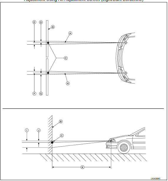
- Headlamp beam (RH)
- Screen
- Horizontal/Vertical center point of headlamp
- 66.5 mm (2.6 in)
- 66.5 mm (2.6 in)
- 66.5 mm (2.6 in)
- 66.5 mm (2.6 in)
- Headlamp beam (LH)
- 53.2 mm (2.1 in)
- 13.3 mm (0.5 in)
- 7.62 m (25 ft)

 Front fog lamp aiming adjustment
Description
PREPARATION BEFORE ADJUSTING
NOTE: For details, refer to the regulations
in your area.
Before performing aiming adjustment, check the following.
Adjust the tire pressure to specif ...
Other materials:
Unit removal and installation
FRONT SUSPENSION ASSEMBLY
Exploded View
Front stabilizer
Stabilizer clamp
Stabilizer bushing
Stabilizer connecting rod
Front mount bracket
Rear mount bracket
Member insulator
Member pin stay
Transverse link
Steering stopper bracket
Stopper bolt cap
Steering stopp ...
Oil
Description
MAINTENANCE OF OIL LEVEL
The compressor oil is circulating in the system together with the
refrigerant. It is necessary to fill compressor with oil when replacing A/C
system parts or when a large amount of refrigerant leakage is detected. It is
important to always maintain oil le ...
Heated seat
Wiring Diagram
...
Nissan Maxima Owners Manual
- Illustrated table of contents
- Safety-Seats, seat belts and supplemental restraint system
- Instruments and controls
- Pre-driving checks and adjustments
- Monitor, climate, audio, phone and voice recognition systems
- Starting and driving
- In case of emergency
- Appearance and care
- Do-it-yourself
- Maintenance and schedules
- Technical and consumer information
Nissan Maxima Service and Repair Manual

0.0058