Nissan Maxima Service and Repair Manual: Front fog lamp aiming adjustment
Description
PREPARATION BEFORE ADJUSTING
NOTE: For details, refer to the regulations in your area.
Before performing aiming adjustment, check the following.
- Adjust the tire pressure to specification.
- Position vehicle and screen on level surface.
- Ensure there is no load in vehicle other than the driver (or equivalent weight placed in driver's position).
- Ensure engine coolant and engine oil are filled to correct levels and fuel tank is full.
- Confirm spare tire, jack and tools are properly stowed.
- Wipe off dirt on the fog lamp.
CAUTION: Do not use organic solvent (thinner, gasoline etc.).
AIMING ADJUSTMENT SCREW
- Turn the aiming adjusting screw for adjustment as shown.
NOTE: A screwdriver or hexagonal wrench [6 mm (0.24 in)] can be used for adjustment.
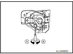
- A: Up
- B: Down
Aiming Adjustment Procedure
NOTE: Set the screen so that it is perpendicular to the road.
- Position the screen.
- Make the distance between the fog lamp center and the screen 7.62 m (25.0 ft).
- Start the engine and illuminate fog lamp. CAUTION: Do not cover the lens surface with tape, etc. because it is made of plastic. NOTE: Block the light from the headlamp that is not being adjusted with a thick fabric or similar object, so that it does not reach the screen..
- Adjust the cutoff line height (A) with the aiming adjustment screw so that the distance (X) between the horizontal center line of front fog lamp (H) and (A) becomes 100 mm (4.0 in).
- Front fog lamp light distribution on the screen is as shown.
- A: Cutoff line
- B: High illuminance area
- H: Horizontal center line of front fog lamp
- V: Vertical center line of front fog lamp
- X: Cutoff line height
 Headlamp aiming adjustment
Description
PREPARATION BEFORE ADJUSTING
CAUTION: Do not use organic solvent
(thinner, gasoline etc.).
NOTE:
For details, refer to the regulations in your own country.
Perform aiming adjust ...

Other materials:
Performance test
Inspection
INSPECTION PROCEDURE
Connect recovery/recycling/recharging equipment (for HFC-134a) or
manifold gauge.
Start the engine, and set to the following condition.
Maintain test condition until A/C system becomes stable. (Approximately
10 minutes)
Check that test results ...
Front tweeter
Removal and Installation
REMOVAL
Remove the front pillar finisher. Refer to INT-24, "Removal and
Installation".
Remove the front tweeter speaker grille. Refer to IP-10, "Exploded
View".
Remove the front tweeter speaker screws (A).
Pull out front tweeter speaker ( ...
Front combination lamp
Disassembly and Assembly
EXPLODED VIEW
Front combination lamp
Xenon bulb
Plastic cover
Side marker lamp socket
Side marker lamp bulb
Front turn signal lamp socket
Front turn signal lamp bulb
Halogen bulb socket (high beam)
Halogen bulb (high beam)
HID control unit and ...
Nissan Maxima Owners Manual
- Illustrated table of contents
- Safety-Seats, seat belts and supplemental restraint system
- Instruments and controls
- Pre-driving checks and adjustments
- Monitor, climate, audio, phone and voice recognition systems
- Starting and driving
- In case of emergency
- Appearance and care
- Do-it-yourself
- Maintenance and schedules
- Technical and consumer information
Nissan Maxima Service and Repair Manual

0.0057