
Nissan Maxima Owners Manual: Automatic operation (if so equipped)
 Manual operation (if so equipped)
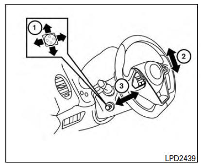
Tilt and telescopic operation
Pull the lock lever 1 down:
Adjust the steering wheel up or down in
direction 2 to the desired position.
Adjust the steering wheel forward or backward
in d ...
 Tilt and telescopic operation
To adjust the steering wheel move the switch 1
in the following directions:
Adjust the steering wheel up or down in
direction 2 to the desired tilt position.
Adjust the steering wheel forward ...
Other materials:
Slip indicator lamp
Description
Component Function Check
1.CHECK SLIP INDICATOR LAMP OPERATION
Check that the lamp illuminates for approximately 2 seconds after the
ignition switch is turned ON.
Diagnosis Procedure
1.CHECK SELF-DIAGNOSIS
Perform ABS actuator and electric unit (control unit) self-diagnosis
...
Emission control system warranty
Your NISSAN vehicle is covered by the following
emission warranties:
For USA
1. Emission Defects Warranty
2. Emissions Performance Warranty
Details of this warranty may be found with other
vehicle warranties in your Warranty Information
Booklet which comes with your NISSAN vehicle.
If you ...
Electronic controlled engine mount
System Diagram
System Description
INPUT/OUTPUT SIGNAL CHART
*: This signal is sent to the ECM via the CAN communication line.
SYSTEM DESCRIPTION
The ECM controls the engine mount operation corresponding to the engine
speed. The control system has a
2-step control [Soft/Hard]
EL ...
Nissan Maxima Owners Manual
- Illustrated table of contents
- Safety-Seats, seat belts and supplemental restraint system
- Instruments and controls
- Pre-driving checks and adjustments
- Monitor, climate, audio, phone and voice recognition systems
- Starting and driving
- In case of emergency
- Appearance and care
- Do-it-yourself
- Maintenance and schedules
- Technical and consumer information
Nissan Maxima Service and Repair Manual

0.0109