Nissan Maxima Service and Repair Manual: Hazard switch
Exploded View
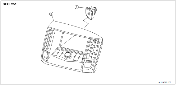
- Hazard switch
- Cluster lid D
Removal and Installation
REMOVAL
- Remove cluster lid D. Refer to IP-18, "Removal and Installation".
- Disconnect the harness connector from the hazard switch.
- Remove the hazard switch.
INSTALLATION
Installation is in the reverse order of remov
 Lighting & turn signal switch
Removal and Installation
NOTE: The lighting and turn signal switch is
integral with the combination switch assembly.
REMOVAL
Unlock steering wheel.
CAUTION:
Before servicing, disconnect ...
 Rear combination lamp
Exploded View
Slide clip
Grommets
Rear combination lamp
Removal and Installation
REAR COMBINATION LAMP
Removal
Remove the trunk side finisher. Refer to INT-36, "Exploded View".
...
Other materials:
RGB (B: blue) signal circuit
Description
Transmit the image displayed with AV control unit with RGB signal to the
display unit.
Diagnosis Procedure
1.CHECK CONTINUITY RGB (B: BLUE) SIGNAL CIRCUIT
Turn ignition switch OFF.
Disconnect display unit connector M141 and AV control unit
connector
M154.
Check con ...
Precaution
Precaution for Supplemental Restraint System (SRS) "AIR BAG" and
"SEAT BELT PRE-TENSIONER"
The Supplemental Restraint System such as "AIR BAG" and "SEAT BELT
PRE-TENSIONER", used along with a front seat belt, helps to reduce the risk
or severity of injury to the driver and front passenger for ...
Conditions the remote start will not work
The remote start will not operate if any of the
following conditions are present:
"Remote Engine Start" is turned off in the
"Locking" section of the Vehicle Settings
menu.
The ignition switch is placed in the ON position.
The hood is not securely closed.
The hazard warning lights are ...
Nissan Maxima Owners Manual
- Illustrated table of contents
- Safety-Seats, seat belts and supplemental restraint system
- Instruments and controls
- Pre-driving checks and adjustments
- Monitor, climate, audio, phone and voice recognition systems
- Starting and driving
- In case of emergency
- Appearance and care
- Do-it-yourself
- Maintenance and schedules
- Technical and consumer information
Nissan Maxima Service and Repair Manual

0.0055