Nissan Maxima Service and Repair Manual: Rear combination lamp
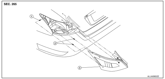
Exploded View

- Slide clip
- Grommets
- Rear combination lamp
Removal and Installation
REAR COMBINATION LAMP
Removal
- Remove the trunk side finisher. Refer to INT-36, "Exploded View".
- Remove the rear combination lamp nuts.
- Pull the rear combination lamp toward the rear of the vehicle to remove it.
- Disconnect the harness connector from the rear combination lamp.
Installation
Installation is in the reverse order of removal.
WARNING: Do not touch bulb with your hand while it is on or right after being turned off, a burn injury may result.
CAUTION:
- Do not touch bulb glass with your hand or keep other grease and oily substances away from bulb glass.
- Do not leave bulb out of lamp reflector for a long time because dust, moisture smoke, etc. may affect the performance of lamp. When replacing bulb, be sure to replace it with new one.
STOP/TAIL LAMP
Replacement is integral with rear combination lamp. Refer to EXL-326, "Exploded View".
REAR SIDE MARKER LAMP BULB
Removal
- Remove the rear combination lamp. Refer to EXL-326, "Exploded View".
- Rotate the rear side marker lamp socket counterclockwise and unlock from rear combination lamp.
- Remove the bulb from the rear side marker lamp socket.
Installation
Installation is in the reverse order of removal.
REAR TURN SIGNAL LAMP BULB
Removal
- Remove the rear combination lamp. Refer to EXL-326, "Exploded View".
- Rotate the rear turn signal lamp socket counterclockwise and unlock from rear combination lamp.
- Remove the bulb from the rear turn signal lamp socket.
Installation
Installation is in the reverse order of removal.
BACK-UP LAMP BULB
Removal
- Remove the rear combination lamp. Refer to EXL-326, "Exploded View".
- Rotate the back-up lamp socket counterclockwise and unlock from rear combination lamp.
- Remove the bulb from the back-up lamp socket.
Installation
Installation is in the reverse order of removal.
 Hazard switch
Exploded View
Hazard switch
Cluster lid D
Removal and Installation
REMOVAL
Remove cluster lid D. Refer to IP-18, "Removal and Installation".
Disconnect the harness connector from th ...
 High-mounted stop lamp
Exploded View
High-mounted stop lamp cover
High-mounted stop lamp bulb
Removal and Installation
REMOVAL
Slide the high-mounted stop lamp rearward on the parcel shelf to
give clearan ...
Other materials:
System maintenance
The two radar sensors 1 for the BSW and
RCTA systems are located near the rear bumper.
Always keep the area near the radar sensors
clean.
The radar sensors may be blocked by temporary
ambient conditions such as splashing water, mist
or fog.
The blocked condition may also be caused b ...
Around View Monitor system operation
With the ignition switch in the ON position, move
the shift lever to the R (Reverse) position or press
the CAMERA button to operate the Around
View Monitor.
When the camera is first activated with the bird'seye
view in the display, a red icon (if so equipped)
will flash on the screen. This i ...
Squeak and rattle trouble diagnoses
Work Flow
CUSTOMER INTERVIEW
Interview the customer if possible, to determine the conditions that exist
when the noise occurs. Use the Diagnostic
Worksheet during the interview to document the facts and conditions when the
noise occurs and any
customer's comments; refer to DLK-199, " ...
Nissan Maxima Owners Manual
- Illustrated table of contents
- Safety-Seats, seat belts and supplemental restraint system
- Instruments and controls
- Pre-driving checks and adjustments
- Monitor, climate, audio, phone and voice recognition systems
- Starting and driving
- In case of emergency
- Appearance and care
- Do-it-yourself
- Maintenance and schedules
- Technical and consumer information
Nissan Maxima Service and Repair Manual
0.0057
