Nissan Maxima Service and Repair Manual: ABS branch line circuit
Diagnosis Procedure
1.CHECK CONNECTOR
- Turn the ignition switch OFF.
- Disconnect the battery cable from the negative terminal.
- Check the terminals and connectors of the ABS actuator and electric unit (control unit) for damage, bend and loose connection (unit side and connector side).
2.CHECK HARNESS FOR OPEN CIRCUIT
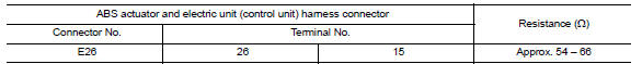
- Disconnect the connector of ABS actuator and electric unit (control unit).
- Check the resistance between the ABS actuator and electric unit (control unit) harness connector terminals.
3.CHECK POWER SUPPLY AND GROUND CIRCUIT
Check the power supply and the ground circuit of the ABS actuator and electric unit (control unit). Refer to BRC-83, "Wiring Diagram".
 A-bag branch line circuit
Diagnosis Procedure
WARNING:
Always observe the following items for preventing accidental
activation.
Before servicing, turn ignition switch OFF, disconnect battery negative
terminal, and wa ...
 TCM branch line circuit
Diagnosis Procedure
1.CHECK CONNECTOR
Turn the ignition switch OFF.
Disconnect the battery cable from the negative terminal.
Check the following terminals and connectors for damage, bend and ...
Other materials:
Fender protector
Exploded View
Front
Front fender protector
Front fender protector side cover
J-clip
Rear
Rear wind deflector
Rear fender protector
Removal and Installation
FRONT FENDER PROTECTOR
Removal
NOTE: Position front tires as necessary to
remove the front fender protect ...
Releasing the trunk lid
Press the button for longer than
1 second
to open the trunk lid. The trunk release button will
not operate when the ignition switch is in the ON
position or when the trunk cancel switch is in the
OFF position. For additional information, refer to
"Cancel switch" in this section. ...
Paddle shifter
Exploded View
Steering column assembly
Paddle shifter (shift-down)
Paddle shifter (shift-up)
Removal and Installation
REMOVAL
Park the vehicle on a level surface.
Remove the driver air bag module. Refer to
SR-12, "Expl ...
Nissan Maxima Owners Manual
- Illustrated table of contents
- Safety-Seats, seat belts and supplemental restraint system
- Instruments and controls
- Pre-driving checks and adjustments
- Monitor, climate, audio, phone and voice recognition systems
- Starting and driving
- In case of emergency
- Appearance and care
- Do-it-yourself
- Maintenance and schedules
- Technical and consumer information
Nissan Maxima Service and Repair Manual

0.0056