Nissan Maxima Service and Repair Manual: TCM branch line circuit
Diagnosis Procedure
1.CHECK CONNECTOR
- Turn the ignition switch OFF.
- Disconnect the battery cable from the negative terminal.
- Check the following terminals and connectors for damage, bend and
loose connection (unit side and connector
side).
- TCM
- Harness connector F1
- Harness connector E3
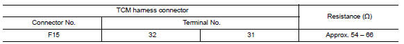
2.CHECK HARNESS FOR OPEN CIRCUIT
- Disconnect the connector of TCM.
- Check the resistance between the TCM harness connector terminals.
3.CHECK POWER SUPPLY AND GROUND CIRCUIT
Check the power supply and the ground circuit of the TCM. Refer to TM-126, "Wiring Diagram".
 ABS branch line circuit
Diagnosis Procedure
1.CHECK CONNECTOR
Turn the ignition switch OFF.
Disconnect the battery cable from the negative terminal.
Check the terminals and connectors of the ABS actuator and
elec ...
 IPDM-E branch line circuit
Diagnosis Procedure
1.CHECK CONNECTOR
Turn the ignition switch OFF.
Disconnect the battery cable from the negative terminal.
Check the terminals and connectors of the IPDM E/R for damage,
...
Other materials:
Washer motor circuit
Diagnosis Procedure
1. CHECK FRONT WASHER MOTOR FUSE
Turn the ignition switch OFF.
Check that the following fuse is not blown.
2. CHECK FRONT WASHER MOTOR POWER SUPPLY
Disconnect front washer motor.
Turn ignition switch ON.
Check voltage between front washer motor harness conne ...
C1105, C1106, C1107, C1108 wheel sensor
DTC Logic
DTC DETECTION LOGIC
DTC CONFIRMATION PROCEDURE
1.CHECK SELF DIAGNOSTIC RESULT
With CONSULT.
Start engine and drive vehicle at approximately 21 km/h (13 MPH)
or more for approximately 5 minutes.
Perform self diagnostic result
Diagnosis Procedure
CAUTION:
Do not check ...
Parking brake control
Exploded View
Parking brake pedal
Parking brake switch
Pedal pad
Adjusting nut
Lock plate
Front cable
Rear cable (RH)
Rear cable (LH)
Equalizer
Spring
Pin
Front
Removal and Installation
REMOVAL
Remove rear wheel and tire using power tool. Refer to ...
Nissan Maxima Owners Manual
- Illustrated table of contents
- Safety-Seats, seat belts and supplemental restraint system
- Instruments and controls
- Pre-driving checks and adjustments
- Monitor, climate, audio, phone and voice recognition systems
- Starting and driving
- In case of emergency
- Appearance and care
- Do-it-yourself
- Maintenance and schedules
- Technical and consumer information
Nissan Maxima Service and Repair Manual

0.0483