Nissan Maxima Service and Repair Manual: IPDM-E branch line circuit
Diagnosis Procedure
1.CHECK CONNECTOR
- Turn the ignition switch OFF.
- Disconnect the battery cable from the negative terminal.
- Check the terminals and connectors of the IPDM E/R for damage, bend and loose connection (unit side and connector side).
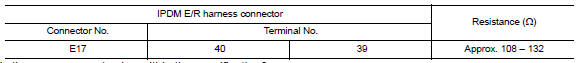
2.CHECK HARNESS FOR OPEN CIRCUIT
- Disconnect the connector of IPDM E/R.
- Check the resistance between the IPDM E/R harness connector terminals.
3.CHECK POWER SUPPLY AND GROUND CIRCUIT
Check the power supply and the ground circuit of the IPDM E/R. Refer to PCS-18, "Diagnosis Procedure".
 TCM branch line circuit
Diagnosis Procedure
1.CHECK CONNECTOR
Turn the ignition switch OFF.
Disconnect the battery cable from the negative terminal.
Check the following terminals and connectors for damage, bend and ...
 CAN communication circuit
Diagnosis Procedure
1.CONNECTOR INSPECTION
Turn the ignition switch OFF.
Disconnect the battery cable from the negative terminal.
Disconnect all the unit connectors on CAN communication syste ...
Other materials:
CAN communication circuit
Diagnosis Procedure
1.CONNECTOR INSPECTION
Turn the ignition switch OFF.
Disconnect the battery cable from the negative terminal.
Disconnect all the unit connectors on CAN communication system.
Check terminals and connectors for damage, bend and loose
connection.
2.CHECK HARNESS CON ...
Magnet clutch control system
System Diagram
System Description
The A/C auto amp. controls compressor operation by ambient temperature,
intake air temperature and signal
from ECM.
SYSTEM OPERATION
When the A/C switch, the AUTO switch, or the DEF switch is pressed, or when
shifting mode position to D/F,
the A/C auto ...
Increasing fuel economy
Keep your engine tuned up.
Follow the recommended scheduled maintenance.
Keep the tires inflated to the correct pressure.
Low tire pressure increases tire wear
and lowers fuel economy.
Keep the wheels in correct alignment. Improper
alignment increases tire wear and
lowers fuel eco ...
Nissan Maxima Owners Manual
- Illustrated table of contents
- Safety-Seats, seat belts and supplemental restraint system
- Instruments and controls
- Pre-driving checks and adjustments
- Monitor, climate, audio, phone and voice recognition systems
- Starting and driving
- In case of emergency
- Appearance and care
- Do-it-yourself
- Maintenance and schedules
- Technical and consumer information
Nissan Maxima Service and Repair Manual

0.0061