Nissan Maxima Service and Repair Manual: Wiring diagram
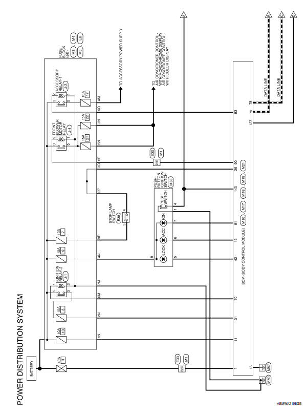
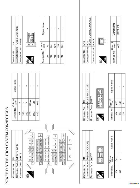
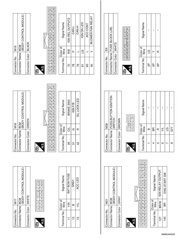
POWER DISTRIBUTION SYSTEM
Wiring Diagram
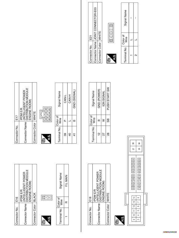
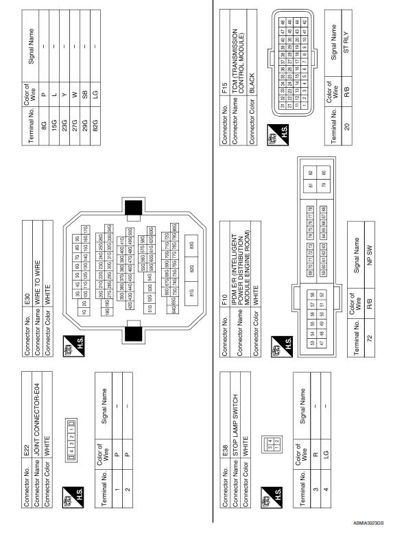
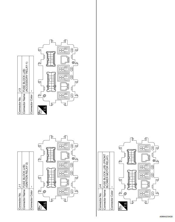
 IPDM E/R (intelligent power distribution module engine room)
Reference Value
VALUES ON THE DIAGNOSIS TOOL
TERMINAL LAYOUT
PHYSICAL VALUES
Fail Safe
CAN COMMUNICATION CONTROL
When CAN communication with ECM and BCM is imposs ...
 Symptom diagnosis
POWER DISTRIBUTION SYSTEM SYMPTOMS
Symptom Table
Before performing the diagnosis in the following table
...
Other materials:
System temporarily unavailable
Condition A
When the radar sensor picks up interference
from another radar source, making it impossible
to detect a vehicle ahead, the PFCW system is
automatically turned off.
The FEB system warning light (orange) will illuminate.
Action to take
When the above conditions no longer exist, th ...
Unit disassembly and assembly
COOLING FAN
Disassembly and Assembly of Cooling Fan
Fan blade
Fan shroud
Fan motor
DISASSEMBLY
Remove fan blade nut.
Remove fan blade from fan motor.
Remove fan motor bolts and remove fan motor from fan shroud.
ASSEMBLY
Assembly is in the reverse order of disassembly. ...
Main line between dlc and hvac circuit
Diagnosis Procedure
1.CHECK HARNESS CONTINUITY (OPEN CIRCUIT)
Turn the ignition switch OFF.
Disconnect the battery cable from the negative
terminal.
Disconnect the following harness connectors.
ECM
A/C auto amp.
Check the continuity betw ...
Nissan Maxima Owners Manual
- Illustrated table of contents
- Safety-Seats, seat belts and supplemental restraint system
- Instruments and controls
- Pre-driving checks and adjustments
- Monitor, climate, audio, phone and voice recognition systems
- Starting and driving
- In case of emergency
- Appearance and care
- Do-it-yourself
- Maintenance and schedules
- Technical and consumer information
Nissan Maxima Service and Repair Manual

0.0066