Nissan Maxima Service and Repair Manual: Inspection and adjustment
ADDITIONAL SERVICE WHEN REMOVING BATTERY NEGATIVE TERMINAL
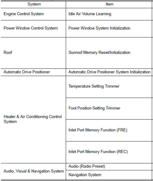
ADDITIONAL SERVICE WHEN REMOVING BATTERY NEGATIVE TERMINAL : Special Repair Requirement
Required Procedure After Battery Disconnection
 Battery
How to Handle Battery
CAUTION:
If it becomes necessary to start the engine with a booster
battery and jumper cables, use a 12-volt
booster battery.
After connecting battery cables, ensure ...

Other materials:
B260f engine status
Description
BCM receives the engine status signal from ECM via CAN
communication.
DTC Logic
DTC DETECTION LOGIC
NOTE:
If DTC B260F is displayed with DTC
U1000, first perform the trouble diagnosis for DTC U1000. Refer to
SEC-29, "DTC Logic".
If DTC B260F is displayed with D ...
P0868 transmission fluid pressure
Description
The secondary pressure solenoid valve regulates the
secondary pressure to suit the driving condition in
response to a signal sent from the TCM.
DTC Logic
DTC DETECTION LOGIC
DTC CONFIRMATION PROCEDURE
CAUTION:
Always drive vehicle at a safe speed.
NOTE:
Immediately after ...
Audio unit
Removal and Installation
Audio unit brackets (LH/RH)
A/C auto amp.
Cluster lid C lower
Audio unit Clip
Pawl
REMOVAL
Disconnect the battery negative terminal. Refer to PG-67, "Removal
and Installation (Battery)".
Remove the cluster lid D. Refer to IP-11, "Removal and ...
Nissan Maxima Owners Manual
- Illustrated table of contents
- Safety-Seats, seat belts and supplemental restraint system
- Instruments and controls
- Pre-driving checks and adjustments
- Monitor, climate, audio, phone and voice recognition systems
- Starting and driving
- In case of emergency
- Appearance and care
- Do-it-yourself
- Maintenance and schedules
- Technical and consumer information
Nissan Maxima Service and Repair Manual

0.005