Nissan Maxima Service and Repair Manual: Battery
How to Handle Battery
CAUTION:
- If it becomes necessary to start the engine with a booster battery and jumper cables, use a 12-volt booster battery.
- After connecting battery cables, ensure that they are tightly clamped to battery terminals for good contact.
- Never add distilled water through the hole used to check specific gravity.
METHODS OF PREVENTING OVER-DISCHARGE
 The following precautions must be taken to prevent over-discharging a
battery.
The following precautions must be taken to prevent over-discharging a
battery.
- The battery surface (particularly its top) should always be kept clean and dry.
- The terminal connections should be clean and tight.
- At every routine maintenance, check the electrolyte level.
This also applies to batteries designated as "low maintenance" and "maintenance-free".
- When the vehicle is not going to be used over a long period of time, disconnect the battery cable from the negative terminal. (If the vehicle has an extended storage switch, turn it off.)
Work Flow
BATTERY DIAGNOSIS WITH EXP-800 NI OR GR8-1200 NI
To diagnose and confirm the condition of the battery, use the following special service tools:
- EXP-800 NI Battery and electrical diagnostic analyzer
- GR8-1200 NI Multitasking battery and electrical diagnostic station
NOTE: Refer to the applicable Instruction Manual for proper battery diagnosis procedures.
BATTERY DIAGNOSIS WITHOUT EXP-800 NI OR GR8-1200 NI
Checking Electrolyte Level
WARNING: Never allow battery fluid to come in contact with skin, eyes, fabrics, or painted surfaces. After touching a battery, never touch or rub your eyes until you have thoroughly washed your hands. If acid contacts eyes, skin or clothing, immediately flush with water for 15 minutes and seek medical attention.
Failure to do this may cause personal injury or damage to clothing or the painted surfaces.
- Remove the cell plug using a suitable tool.
- Add distilled water up to the MAX level.
SULFATION
- A battery will be completely discharged if it is left unattended for a long time and the specific gravity will become less than 1.100. This may result in sulfation on the cell plates.
- To determine if a battery has been "sulfated", note its voltage and current when charging it. As shown in the figure, less current and higher voltage are observed in the initial stage of charging sulfated batteries.
- A sulfated battery may sometimes be brought back into service by means of a long, slow charge, 12 hours or more, followed by a battery capacity test.
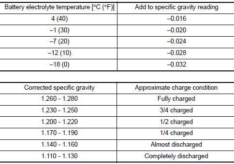
Specific Gravity Check
NOTE: Check the charge condition of the battery.
Periodically check the specific gravity of the electrolyte. Keep a close check on charge condition to prevent over-discharge.
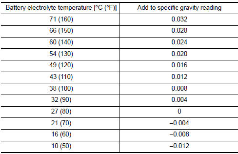
- Read hydrometer and thermometer indications at eye level.
- Use the chart below to correct your hydrometer reading according to electrolyte temperature.
Hydrometer Temperature Correction
Charging The Battery
CAUTION:
- Never "quick charge" a fully discharged battery.
- Keep the battery away from open flame while it is being charged.
- When connecting the charger, connect the leads first, then turn on the charger. Never turn on the charger first, as this may cause a spark.
- If battery electrolyte temperature rises above 55 C (131 F), stop charging. Always charge battery at a temperature below 55 C (131 F).
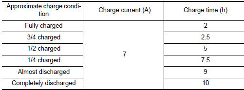
Charging Rates (Standard Charge)
Charging Rates (Quick Charge)
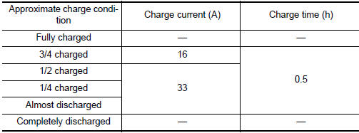
NOTE: The ammeter reading on your battery charger will automatically decrease as the battery charges. This indicates that the voltage of the battery is increasing normally as the state of charge improves. The charging amps indicated above refer to initial charge rate.
- If, after charging, the specific gravity of any two cells varies more than 0.050, the battery should be replaced.
 Basic inspection
...
 Inspection and adjustment
ADDITIONAL SERVICE WHEN REMOVING BATTERY NEGATIVE TERMINAL
ADDITIONAL SERVICE WHEN REMOVING BATTERY NEGATIVE TERMINAL : Special
Repair Requirement
Required Procedure After Battery Disconnection
...
Other materials:
P0453 evap control system pressure sensor
Description
The EVAP control system pressure sensor detects pressure in the
purge line. The sensor output voltage to the ECM increases as pressure
increases.
DTC Logic
DTC DETECTION LOGIC
DTC CONFIRMATION PROCEDURE
1.PRECONDITIONING
If DTC Confirmation Procedure has been previously ...
RGB (R: red) signal circuit
Description
Transmit the image displayed with AV control unit with RGB signal to the
display unit.
Diagnosis Procedure
1.CHECK CONTINUITY RGB (R: RED) SIGNAL CIRCUIT
Turn ignition switch OFF.
Disconnect display unit connector M141 and AV control unit
connector M117.
Check continu ...
Exhaust Manifold And Three Way Catalyst
Exploded View
Gasket
Exhaust manifold (RH)
Exhaust manifold heat shield (RH)
Air fuel ratio sensor 1 (bank 1)
Ring gasket
Three way catalyst (bank 1)
Three way catalyst support (bank 1)
Heated oxygen sensor 2 (bank 1)
Three way catalyst (bank 2)
Three way catalyst suppor ...
Nissan Maxima Owners Manual
- Illustrated table of contents
- Safety-Seats, seat belts and supplemental restraint system
- Instruments and controls
- Pre-driving checks and adjustments
- Monitor, climate, audio, phone and voice recognition systems
- Starting and driving
- In case of emergency
- Appearance and care
- Do-it-yourself
- Maintenance and schedules
- Technical and consumer information
Nissan Maxima Service and Repair Manual

0.0052