Nissan Maxima Service and Repair Manual: B2578, B2579 in-vehicle sensor
Description
In-vehicle Sensor
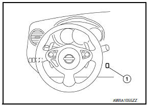
- The in-vehicle sensor (1) is located on instrument lower cover (LH).
- It converts variations in compartment air temperature drawn from the aspirator into a resistance value. It is then input into the A/C auto amp.
In-vehicle Sensor Circuit
Aspirator
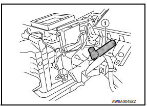
The aspirator (1) is located on driver side of heater & cooling unit assembly. It produces vacuum pressure due to air discharged from the heater & cooling unit assembly, continuously taking compartment air in the aspirator.
DTC Logic
DTC DETECTION LOGIC
NOTE: If DTC is displayed along with DTC U1000 or U1010, first diagnose the DTC U1000 or U1010.
DTC CONFIRMATION PROCEDURE
1.CHECK WITH SELF-DIAGNOSIS FUNCTION OF CONSULT
- Using CONSULT, perform "SELF-DIAGNOSIS RESULTS" of HVAC.
- Check if any DTC No. is displayed in the self-diagnosis results.
NOTE: If DTC is displayed along with DTC U1000 or U1010, first diagnose the DTC U1000 or U1010.
Diagnosis Procedure
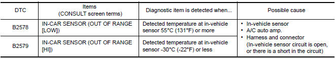
1.CHECK IN-VEHICLE SENSOR POWER SUPPLY
- Disconnect in-vehicle sensor connector.
- Turn ignition switch ON.
- Check voltage between in-vehicle sensor harness connector M34 terminal 1 and ground.
1 - Ground: Approx. 5V
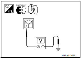
2.CHECK CONTINUITY BETWEEN IN-VEHICLE SENSOR AND A/C AUTO AMP.
- Turn ignition switch OFF.
- Disconnect A/C auto amp. connector.
- Check continuity between in-vehicle sensor harness connector M34 (A) terminal 2 and A/C auto amp. harness connector M37 (B) terminal 37.
2 - 37: Continuity should exist.
3.CHECK IN-VEHICLE SENSOR
Check in-vehicle sensor.
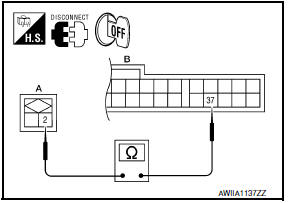
4.CHECK CONTINUITY BETWEEN IN-VEHICLE SENSOR AND A/C AUTO AMP.
- Turn ignition switch OFF.
- Disconnect A/C auto amp. connector.
- Check continuity between in-vehicle sensor harness connector M34 (A) terminal 1 and A/C auto amp. harness connector M37 (B) terminal 36.
1 - 36: Continuity should exist.
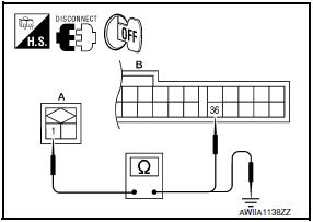
- Check continuity between in-vehicle sensor harness connector M34 (A) terminal 1 and ground.
1 - Ground: Continuity should not exist.
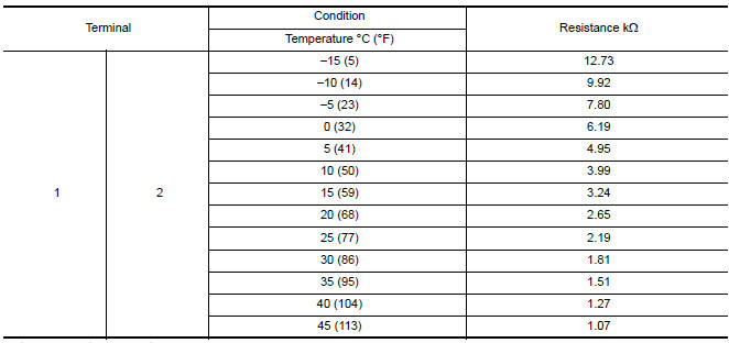
Component Inspection
1.CHECK IN-VEHICLE SENSOR
- Turn ignition switch OFF.
- Disconnect in-vehicle sensor connector.
- Check resistance between in-vehicle sensor terminals.
 B257B, B257C ambient sensor
Description
COMPONENT DESCRIPTION
Ambient Sensor
The ambient sensor (1) is installed to the front bumper
reinforcement.
It detects ambient temperature and converts it into a resistance
...
 B2581, B2582 intake sensor
Description
Intake Sensor
The intake sensor is located on the evaporator.
It converts air temperature after it passes through the evaporator
into a resistance value which is then input to ...
Other materials:
Drive Belts
Checking Drive Belts
Idler pulley
Drive belt
Power steering oil pump
Drive belt auto-tensioner
Crankshaft pulley
Idler pulley
A/C compressor
Generator
Indicator
New drive belt range
Possible use range
View D
Engine front
WARNING: Inspect and check the dri ...
Service data and specifications (SDS)
Steering Wheel
Steering Angle
Steering Column
STEERING COLUMN LENGTH
STEERING COLUMN ROTATING TORQUE
TILT MECHANISM OPERATING RANGE
Steering Gear
STEERING OUTER SOCKET AND INNER SOCKET
RACK STROKE
RACK SLIDING FORCE
Oil Pump
Steering Fluid
...
Glove box assembly
Removal and Installation
REMOVAL
Using a suitable tool, gently remove the instrument panel side
finisher (RH).
Open the glove box door and then remove the glove box assembly
screws (A).
Remove the glove box assembly lower screws (A).
Disconnect the harness connectors, then rem ...
Nissan Maxima Owners Manual
- Illustrated table of contents
- Safety-Seats, seat belts and supplemental restraint system
- Instruments and controls
- Pre-driving checks and adjustments
- Monitor, climate, audio, phone and voice recognition systems
- Starting and driving
- In case of emergency
- Appearance and care
- Do-it-yourself
- Maintenance and schedules
- Technical and consumer information
Nissan Maxima Service and Repair Manual

0.0062