Nissan Maxima Service and Repair Manual: B2581, B2582 intake sensor
Description
Intake Sensor
- The intake sensor is located on the evaporator.
- It converts air temperature after it passes through the evaporator into a resistance value which is then input to the A/C auto amp.
Intake Sensor Circuit
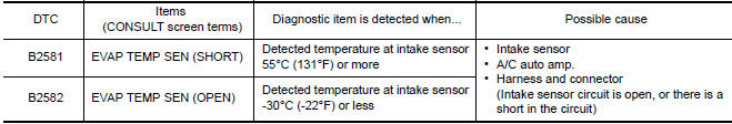
DTC Logic
DTC DETECTION LOGIC
NOTE: If DTC is displayed along with DTC U1000 or U1010, first diagnose the DTC U1000 or U1010. Refer to HAC- 30, "DTC Logic" or HAC-31, "DTC Logic".
DTC CONFIRMATION PROCEDURE
1.CHECK WITH SELF-DIAGNOSIS FUNCTION OF CONSULT
- Using CONSULT, perform "SELF-DIAGNOSIS RESULTS" of HVAC.
- Check if any DTC No. is displayed in the self-diagnosis results.
NOTE: If DTC is displayed along with DTC U1000 or U1010, first diagnose the DTC U1000 or U1010.
Diagnosis Procedure
1.CHECK INTAKE SENSOR POWER SUPPLY
- Disconnect intake sensor connector.
- Turn ignition switch ON.
- Check voltage between intake sensor harness connector M69 terminal 1 and ground.
1 - Ground: Approx. 5V
2.CHECK CONTINUITY BETWEEN INTAKE SENSOR AND A/C AUTO AMP.
- Turn ignition switch OFF.
- Disconnect A/C auto amp. connector.
- Check continuity between intake sensor harness connector M69 (A) terminal 2 and A/C auto amp. harness connector M37 (B) terminal 37.
2 - 37: Continuity should exist.
3.CHECK INTAKE SENSOR
Check intake sensor.
4.CHECK CONTINUITY BETWEEN INTAKE SENSOR AND A/C AUTO AMP.
- Turn ignition switch OFF.
- Disconnect A/C auto amp. connector.
- Check continuity between intake sensor harness connector M69 (A) terminal 1 and A/C auto amp. harness connector M37 (B) terminal 16.
1 - 16: Continuity should exist.
- Check continuity between intake sensor harness connector M69 (A) terminal 1 and ground
1 - Ground: Continuity should not exist.
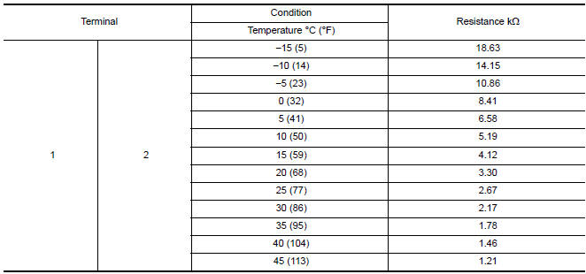
Component Inspection
1.CHECK INTAKE SENSOR
- Turn ignition switch OFF.
- Disconnect intake sensor connector.
- Check resistance between intake sensor terminals
 B2578, B2579 in-vehicle sensor
Description
In-vehicle Sensor
The in-vehicle sensor (1) is located on instrument lower cover
(LH).
It converts variations in compartment air temperature drawn from
the aspirator into a resi ...
 B2630, B2631 sunload sensor
Description
COMPONENT DESCRIPTION
Sunload Sensor
The sunload sensor (1) is located on the driver'side defroster
grille.
It detects sunload entering through windshield by means of a
photo ...
Other materials:
U1243 display unit
Description
Part name
Description
DISPLAY UNIT
Display image is controlled by the serial communication from AV
control unit.
Inputs the RGB image signal (RGB, RGB area and RGB
synchronizing) from AV control unit and the auxiliary image ...
U1243 display unit
DTC Logic
Diagnosis Procedure
1.CHECK DISPLAY UNIT POWER SUPPLY AND GROUND CIRCUIT
Check display unit power supply and ground circuit
2.CHECK CONTINUITY OF COMMUNICATION CIRCUIT
Turn ignition switch OFF.
Disconnect display unit connector M142 and AV control unit
connector M163.
...
Front drive shaft
Removal and Installation (LH)
Drive shaft
Cotter pin
REMOVAL
Remove wheel and tire using power tool. Refer to WT-60, "Adjustment".
Remove wheel sensor from steering knuckle. Refer to BRC-102,
"Removal and Installation - Front Wheel Sensor".CAUTION: Do not
pull o ...
Nissan Maxima Owners Manual
- Illustrated table of contents
- Safety-Seats, seat belts and supplemental restraint system
- Instruments and controls
- Pre-driving checks and adjustments
- Monitor, climate, audio, phone and voice recognition systems
- Starting and driving
- In case of emergency
- Appearance and care
- Do-it-yourself
- Maintenance and schedules
- Technical and consumer information
Nissan Maxima Service and Repair Manual

0.006