Nissan Maxima Service and Repair Manual: Display unit
Reference Value
TERMINAL LAYOUT
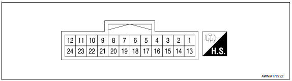
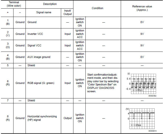
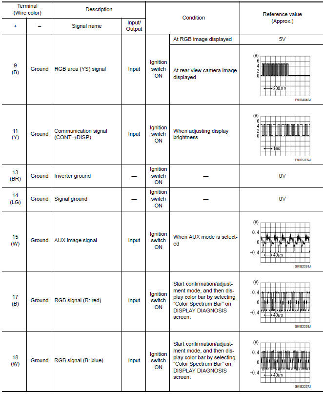
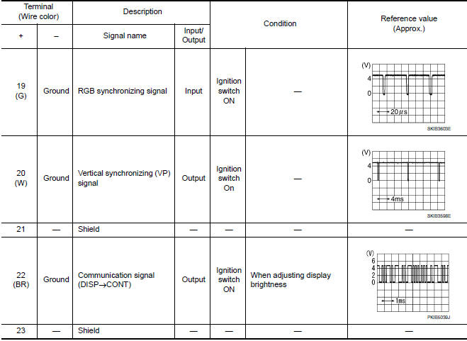
PHYSICAL VALUES
 AV control unit
Reference Value
VALUES ON THE DIAGNOSIS TOOL
TERMINAL LAYOUT
PHYSICAL VALUES
DTC Index
Self-diagnosis results display item
...
 Subwoofer AMP
Reference Value
TERMINAL LAYOUT
PHYSICAL VALUES
...
Other materials:
Slip indicator lamp
Description
Component Function Check
1.CHECK SLIP INDICATOR LAMP OPERATION
Check that the lamp illuminates for approximately 2 seconds after the
ignition switch is turned ON.
Diagnosis Procedure
1.CHECK SELF-DIAGNOSIS
Perform ABS actuator and electric unit (control unit) self-diagnosis
...
Signal buffer system
System Diagram
System Description
IPDM E/R reads the status of the oil pressure switch and transmits the
oil pressure switch signal to BCM via
CAN communication.
IPDM E/R receives the rear window defogger status signal from BCM
via CAN communication and transmits
it to ECM via ...
System malfunction
If the FEB system malfunctions, it will be turned
off automatically, a chime will sound, the FEB
warning light (orange) will illuminate and the
warning message [Malfunction] will appear in the
vehicle information display.
Action to take
If the warning light (orange) comes on, stop the
vehicle ...
Nissan Maxima Owners Manual
- Illustrated table of contents
- Safety-Seats, seat belts and supplemental restraint system
- Instruments and controls
- Pre-driving checks and adjustments
- Monitor, climate, audio, phone and voice recognition systems
- Starting and driving
- In case of emergency
- Appearance and care
- Do-it-yourself
- Maintenance and schedules
- Technical and consumer information
Nissan Maxima Service and Repair Manual

0.0068