Nissan Maxima Service and Repair Manual: Audio system
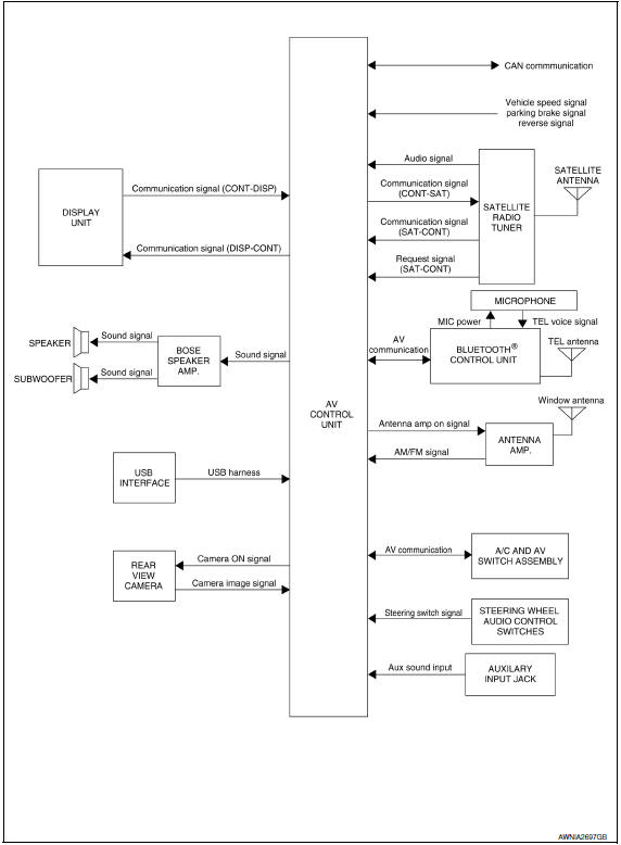
System Diagram
System Description
AUDIO SYSTEM
The audio system consists of the following components
- AV control unit
- Display unit
- BOSE speaker amp.
- Window antenna
- Steering wheel audio control switches
- A/C and AV switch assembly
- Front door speakers
- Tweeters
- Center speaker
- Rear door speakers
- Rear subwoofer
When the audio system is on, radio signals are received by the window antenna. The AV control unit then sends audio signals to the BOSE speaker amp. The BOSE speaker amp. amplifies the audio signals before sending them to the front door speakers, tweeters, center speaker, rear door speakers and rear subwoofers.
Refer to Owner's Manual for audio system operating instructions.
SATELLITE RADIO SYSTEM (IF EQUIPPED)
The satellite radio system consists of the following components
- Satellite antenna
- Satellite radio tuner
When the satellite radio system is on, radio signals are supplied to the satellite radio tuner from the satellite antenna. The satellite radio tuner then sends audio signals to the AV control unit.
Refer to Owner's Manual for satellite radio system operating instructions.
SPEED SENSITIVE VOLUME SYSTEM
Volume level of this system goes up and down automatically in proportion to the vehicle speed. The control level can be selected by the customer. Refer to Owner's Manual for operating instructions.
Component Parts Location
- Tweeter LH M51
- Center speaker M130
- Tweeter RH M52
- AV control unit M152, M153, M154, M155, M156, M157, M158, M159 (located behind A/C and AV switch assembly)
- Display unit M141
- A/C and AV switch assembly M98
- Steering angle sensor M53 [located in steering column behind combination switch(spiral cable)]
- Steering wheel audio control switches
- USB interface M211 (view in center console)
- Aux jack M209 11. Rear subwoofers (view under rear parcel shelf) LH B106 RH B107
- Satellite radio tuner (if equipped) B111
- Bluetooth control unit B128, B130, B131
- BOSE speaker amp B109, B110
- Microphone R7
- Rear view camera T101
- Front door speaker LH D3 RH D103
- Rear door speaker LH D202 RH D302
Component Description
| Part name | Description |
| AV control unit | Controls audio system, USB connection,AUX IN connection and satellite radio system functions |
| Display unit | Displays all audio and climate control related information |
| BOSE speaker amp. | Receives power (amp ON) and audio signals from AV control unit and outputs audio signals to each speaker. |
| Steering wheel audio control switches |
|
| Front door speakers |
|
| Tweeters |
|
| Center speaker |
|
| Rear door speakers |
|
| Rear subwoofer |
|
| Satellite radio tuner (if equipped) |
|
| Satellite antenna (if equipped) | Audio signal (satellite radio) is received and output to AV control unit. |

 Rear view monitor system
System Diagram
System Description
When the shift selector is in the R position, the display shows a view to the
rear of the vehicle. Lines which indicate the vehicle clearance and distances
ar ...
Other materials:
NISSAN vehicle immobilizer system
The NISSAN Vehicle Immobilizer System will not
allow the engine to start without the use of a
registered key.
If the engine fails to start using a registered key
(for example, when interference is caused by
another registered key, an automated toll road
device or automatic payment device on ...
Turn signal switch
Turn signal
Move the lever up or down until it latches to
signal the turning direction. When the turn is
completed, the turn signal cancels automatically.
Lane change signal
Move the lever up or down until the turn
signal begins to flash, but the lever does not
latch, to signa ...
Driver Attention Alert system limitations
WARNING
Listed below are the system limitations for
the Driver Attention Alert system. Failure
to operate the vehicle in accordance with
these system limitations could result in
serious injury or death.
The Driver Attention Alert system may
not operate properly and may not provide
an alert i ...
Nissan Maxima Owners Manual
- Illustrated table of contents
- Safety-Seats, seat belts and supplemental restraint system
- Instruments and controls
- Pre-driving checks and adjustments
- Monitor, climate, audio, phone and voice recognition systems
- Starting and driving
- In case of emergency
- Appearance and care
- Do-it-yourself
- Maintenance and schedules
- Technical and consumer information
Nissan Maxima Service and Repair Manual

0.0064