Nissan Maxima Service and Repair Manual: Audio antenna
Location of Antenna
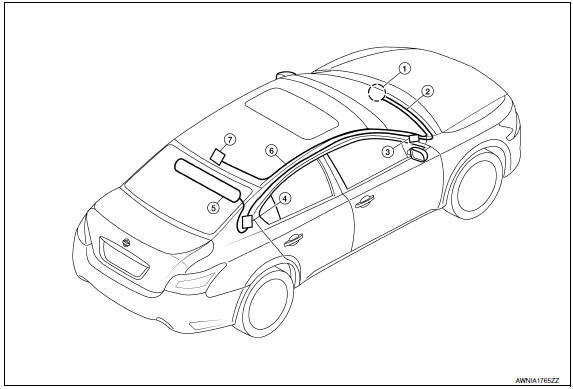
- AV control unit
- AV control unit antenna feeder
- In-line connectors M103, M501
- Antenna amp.
- Window antenna
- Satellite radio antenna feeder
- Satellite radio antenna
Window Antenna Repair
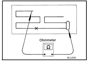
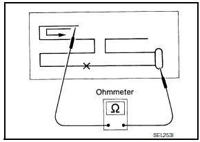
ELEMENT CHECK
- Attach probe circuit tester (ohm setting) to antenna terminal on each side
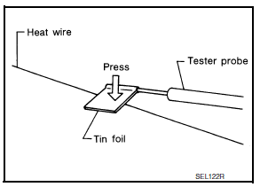
- When measuring continuity, wrap tin foil around the top of probe. Then, press the foil against the wire with your finger.
- If an element is broken, no continuity will exist.
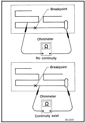
- To locate a break, move probe along element. Tester indication will change abruptly when probe passes the broken point.
REPAIR EQUIPMENT
- Conductive silver composition (DuPont No. 4817 or equivalent)
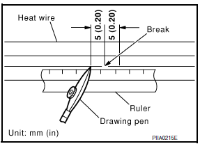
- Ruler 30 cm (11.8 in) long
- Drawing pen
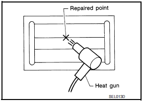
- Heat gun
- Alcohol
- Cloth
REPAIRING PROCEDURE
- Wipe broken heat wire and its surrounding area clean with a cloth dampened in alcohol.
- Apply a small amount of conductive silver composition to tip of drawing pen. NOTE: Shake silver composition container before use.
- Place ruler on glass along broken line. Deposit conductive silver composition on break with drawing pen. Slightly overlap existing heat wire on both sides [preferably 5 mm (0.20 in)] of the break.
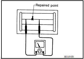
- After repair has been completed, check repaired wire for continuity.
This check should be conducted 10 minutes after silver composition is deposited.
Do not touch repaired area while test is being conducted.
- After repair has been completed, check repaired wire for continuity.
This check should be conducted 10 minutes after silver composition is deposited.
Do not touch repaired area while test is being conducted.
 Steering switch
Removal and Installation
REMOVAL
Remove the driver airbag module. Refer to SR-12, "Removal and
Installation".
Remove the steering wheel audio control switch screws (A).
Release t ...
 Antenna AMP.
Removal and Installation
REMOVAL
Remove the rear pillar finisher RH. Refer to INT-36, "Exploded
View".
Detach the antenna amp. harness clip (A).
Disconnect the harness connectors ...
Other materials:
Hazard function
Symptom Table
HAZARD AND BUZZER REMINDER FUNCTION MALFUNCTION
NOTE:
Before performing the diagnosis in the following table, check
"Work flow". Refer to DLK-9, "Work Flow".
If the following symptoms are detected, check systems shown in
the "Diagnosis/service procedure" column ...
Precautions
Precaution for Supplemental Restraint System (SRS) "AIR BAG" and "SEAT
BELT
PRE-TENSIONER"
The Supplemental Restraint System such as "AIR BAG" and "SEAT BELT
PRE-TENSIONER", used along
with a front seat belt, helps to reduce the risk or severity of injury to the
driver ...
P0460 fuel level sensor
Description
The fuel level sensor is mounted in the fuel level sensor unit.
The sensor detects a fuel level in the fuel tank and transmits a signal to the
combination meter. The combination
meter sends the fuel level sensor signal to the ECM via the CAN communication
line.
It consists o ...
Nissan Maxima Owners Manual
- Illustrated table of contents
- Safety-Seats, seat belts and supplemental restraint system
- Instruments and controls
- Pre-driving checks and adjustments
- Monitor, climate, audio, phone and voice recognition systems
- Starting and driving
- In case of emergency
- Appearance and care
- Do-it-yourself
- Maintenance and schedules
- Technical and consumer information
Nissan Maxima Service and Repair Manual

0.0057