Nissan Maxima Service and Repair Manual: Fuel pump
Description
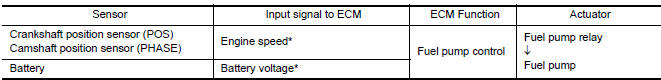
*: ECM determines the start signal status by the signals of engine speed and battery voltage.
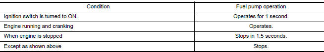
The ECM activates the fuel pump for several seconds after the ignition switch is turned ON to improve engine start ability. If the ECM receives a engine speed signal from the camshaft position sensor (PHASE), it knows that the engine is rotating, and causes the pump to operate. If the engine speed signal is not received when the ignition switch is ON, the engine stalls. The ECM stops pump operation and prevents battery discharging, thereby improving safety. The ECM does not directly drive the fuel pump. It controls the ON/OFF fuel pump relay, which in turn controls the fuel pump.
Component Function Check
1.CHECK FUEL PUMP FUNCTION
- Turn ignition switch ON.
- Pinch fuel feed hose with two fingers.
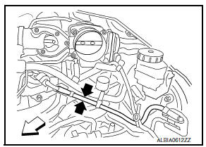
 : Vehicle front (Illustration
shows
the view with intake air duct removed)
: Vehicle front (Illustration
shows
the view with intake air duct removed)
Fuel pressure pulsation should be felt on the fuel feed hose for 1 second after ignition switch is turned ON.
Diagnosis Procedure
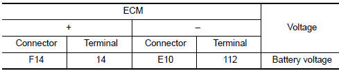
1.CHECK FUEL PUMP POWER SUPPLY CIRCUIT-I
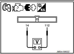
- Turn ignition switch OFF.
- Disconnect ECM harness connector.
- Turn ignition switch ON.
- Check the voltage between ECM harness connector and ground.
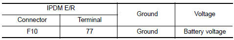
2.CHECK FUEL PUMP POWER SUPPLY CIRCUIT-II
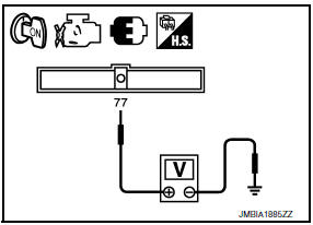
Check the voltage between IPDM E/R harness connector and ground.
3.DETECT MALFUNCTIONING PART
Check the following.
- IPDM E/R harness connector F10
- Harness for open or short between IPDM E/R and ECM
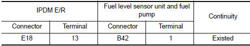
4.CHECK FUEL PUMP POWER SUPPLY CIRCUIT-III
- Disconnect "fuel level sensor unit and fuel pump" harness connector.
- Check harness continuity between IPDM E/R harness connector and "fuel level sensor unit and fuel pump" harness connector
5.DETECT MALFUNCTIONING PART
Check the following.
- Harness connectors B10, E29
- Harness for open or short between "fuel level sensor unit and fuel pump" and IPDM E/R
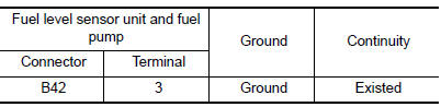
6.CHECK FUEL PUMP GROUND CIRCUIT
- Disconnect "fuel level sensor unit and fuel pump" harness connector.
- Check the continuity between "fuel level sensor unit and fuel pump" harness connector and ground.
7.CHECK FUEL PUMP
8.CHECK INTERMITTENT INCIDENT
Component Inspection
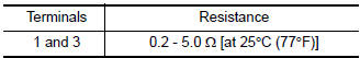
1.CHECK FUEL PUMP
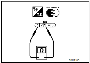
- Turn ignition switch OFF.
- Disconnect "fuel level sensor unit and fuel pump" harness connector.
- Check resistance between "fuel level sensor unit and fuel pump" terminals as per the following.
 Fuel injector
Description
The fuel injector is a small, precise solenoid valve. When the ECM
supplies a ground to the fuel injector circuit, the coil in the fuel injector
is energized. The energized coil p ...
 Ignition signal
Description
The ignition signal from the ECM is sent to and amplified by the power
transistor. The power transistor turns
ON and OFF the ignition coil primary circuit. This ON/OFF operation induc ...
Other materials:
Disassembly and assembly
FUEL LEVEL SENSOR UNIT
Disassembly and Assembly
Fuel Level Sensor Unit
Harness connectors
Fuel level sensor unit
Fuel tank temperature sensor
Float arm assembly
Disassembly
NOTE: Before disassembly, note the proper
placement of the wires to the correct terminals a ...
Vehicle speed signal circuit
Description
Combination meter sends vehicle speed signal to power steering control unit.
Diagnosis Procedure
1.PERFORM COMBINATION METER SELF-DIAGNOSIS
Perform combination meter self-diagnosis.
2.CHECK HARNESS BETWEEN COMBINATION METER AND POWER STEERING CONTROL UNIT FOR
OPEN
Turn the ...
P0746 pressure control solenoid A
Description
The line pressure solenoid valve regulates the oil pump discharge pressure to
suit the driving condition in
response to a signal sent from the TCM.
DTC Logic
DTC DETECTION LOGIC
DTC CONFIRMATION PROCEDURE
CAUTION:
Always drive vehicle at a safe speed.
NOTE:
Immediately af ...
Nissan Maxima Owners Manual
- Illustrated table of contents
- Safety-Seats, seat belts and supplemental restraint system
- Instruments and controls
- Pre-driving checks and adjustments
- Monitor, climate, audio, phone and voice recognition systems
- Starting and driving
- In case of emergency
- Appearance and care
- Do-it-yourself
- Maintenance and schedules
- Technical and consumer information
Nissan Maxima Service and Repair Manual

0.0054