Nissan Maxima Service and Repair Manual: Precaution
PRECAUTIONS
Precaution for Supplemental Restraint System (SRS) "AIR BAG" and "SEAT BELT PRE-TENSIONER"
The Supplemental Restraint System such as "AIR BAG" and "SEAT BELT PRE-TENSIONER", used along with a front seat belt, helps to reduce the risk or severity of injury to the driver and front passenger for certain types of collision. This system includes seat belt switch inputs and dual stage front air bag modules. The SRS system uses the seat belt switches to determine the front air bag deployment, and may only deploy one front air bag, depending on the severity of a collision and whether the front occupants are belted or unbelted.
Information necessary to service the system safely is included in the SR and SB section of this Service Manual.
WARNING:
- To avoid rendering the SRS inoperative, which could increase the risk of personal injury or death in the event of a collision which would result in air bag inflation, all maintenance must be performed by an authorized NISSAN/INFINITI dealer.
- Improper maintenance, including incorrect removal and installation of the SRS, can lead to personal injury caused by unintentional activation of the system. For removal of Spiral Cable and Air Bag Module, see the SR section.
- Do not use electrical test equipment on any circuit related to the SRS unless instructed to in this Service Manual. SRS wiring harnesses can be identified by yellow and/or orange harnesses or harness connectors.
PRECAUTIONS WHEN USING POWER TOOLS (AIR OR ELECTRIC) AND HAMMERS
WARNING:
- When working near the Airbag Diagnosis Sensor Unit or other Airbag System sensors with the Ignition ON or engine running, DO NOT use air or electric power tools or strike near the sensor(s) with a hammer. Heavy vibration could activate the sensor(s) and deploy the air bag(s), possibly causing serious injury.
- When using air or electric power tools or hammers, always switch the Ignition OFF, disconnect the battery, and wait at least 3 minutes before performing any service.
General Precaution
WARNING: When replacing fuel line parts, be sure to observe the following.
- Put a "CAUTION: FLAMMABLE" sign in the work area.
- Be sure to work in a well ventilated area and have a CO2 fire extinguisher.
- Do not smoke while working on the fuel system. Keep open flames and sparks away from the work area.
CAUTION:
- - Before removing fuel line parts, carry out the following procedures:
- Put drained fuel in an explosion-proof container and put the lid on securely. Keep the container in safe area.
- Release fuel pressure from the fuel lines. Refer to EC-592, "Inspection".
- Disconnect the battery ground cable.
- Always replace O-rings and clamps with new ones.
- Do not kink or twist tubes when they are being installed.
- Do not tighten hose clamps excessively to avoid damaging hoses.
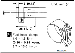
Tighten high-pressure rubber hose clamp so that clamp end is 3 mm (0.12 in) from hose end.
Tightening torque specifications are the same for all rubber hose clamps.
Ensure that screw does not contact adjacent parts.
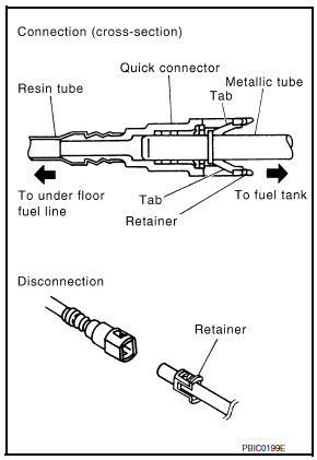
- After connecting the fuel tube quick connectors, make sure the quick
connectors are secure.
Check that the connector and resin tube do not contact any adjacent parts.
- a) Apply fuel pressure to the fuel system by turning the ignition switch to ON (without starting the engine). Then check for fuel leaks at the fuel tube connections.
- b) Start the engine and rev the engine, then check for fuel leaks at the fuel tube connections.
- After installing the tubes, run the engine and check for fuel leaks at the connections.
- Use only a Genuine NISSAN fuel filler cap as a replacement. If an incorrect fuel filler cap is used, the MIL may come on.
- For servicing "Evaporative Emission System" parts, refer to EC-94, "System Description".
 Fuel system
...
 Preparation
PREPARATION
Special Service Tool
The actual shapes of the tools may differ from those illustrated here.
Commercial Service Tool
...
Other materials:
Rear sunshade
Removal and Installation
Rear sunshade unit Front
REMOVAL
Remove the rear parcel shelf finisher. Refer to INT-24, "Removal
and Installation".
Remove the rear sunshade unit.
Remove the rear sunshade unit bolts.
Disconnect the rear sunshade unit harness
connector ...
Tilt switch
Description
ADP steering switch (tilt switch) is equipped to the steering column. The
operation signal is input to the automatic drive positioner control unit when
the tilt switch is operated.
Component Function Check
1. CHECK FUNCTION
Select "TILT SW-UP", "TILT SW-DOWN" in "DATA MONITOR" ...
Steering switch
Description
When one of the steering wheel audio control switches is pushed, the
resistance in the steering wheel audio
control switch circuit changes, depending on which button is pushed.
Diagnosis Procedure
1.CHECK STEERING WHEEL AUDIO CONTROL SWITCH RESISTANCE
Turn ignition switch ...
Nissan Maxima Owners Manual
- Illustrated table of contents
- Safety-Seats, seat belts and supplemental restraint system
- Instruments and controls
- Pre-driving checks and adjustments
- Monitor, climate, audio, phone and voice recognition systems
- Starting and driving
- In case of emergency
- Appearance and care
- Do-it-yourself
- Maintenance and schedules
- Technical and consumer information
Nissan Maxima Service and Repair Manual

0.0054