Nissan Maxima Service and Repair Manual: Disassembly and assembly
FUEL LEVEL SENSOR UNIT
Disassembly and Assembly
Fuel Level Sensor Unit
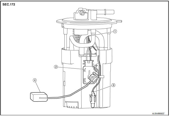
- Harness connectors
- Fuel level sensor unit
- Fuel tank temperature sensor
- Float arm assembly
Disassembly
NOTE: Before disassembly, note the proper placement of the wires to the correct terminals and correct wire routing to the terminals.
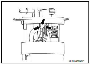
- Disconnect the red, white, and double black wire connectors.
- Press the tabs on the terminals to release the locking tabs
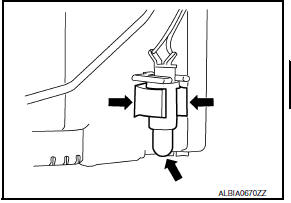
- Release the two clips and remove the fuel tank temperature sensor from the pump assembly.
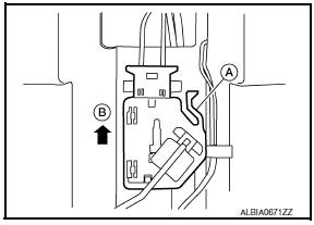
- Release the tab (A) and slide the fuel level sensor unit and float arm assembly (B) up to remove.
Assembly
NOTE: Assembly is the reverse order of disassembly.
- Ensure proper placement of the wires to the correct terminals and correct wire routing to the terminals.
- After connecting terminals, ensure they are securely locked and can not be pulled out.
- When installing the fuel level sensor unit, push down until the tab is locked into place.
 EVAP control system pressure sensor
Removal and Installation
REMOVAL
Remove rear stabilizer bar clamps and position rear stabilizer bar
aside. Refer to RSU-13, "Removal and Installation".
Disconnect EVAP hose from ...
 Service data and specifications (SDS)
SERVICE DATA AND SPECIFICATIONS (SDS)
Fuel Tank
Standard and Limit
...
Other materials:
Front door speaker
Description
The AV control unit sends audio signals to the front door speakers using the
front door speaker circuits.
Diagnosis Procedure
1.CONNECTOR CHECK
Check the AV control unit and speaker connectors for the following:
Proper connection
Damage
Disconnected or loose terminals
2. ...
Audio system
Symptom Table
AUDIO SYSTEM
RELATED TO HANDS-FREE PHONE
Before performing diagnosis, confirm that the cellular phone being
used by the customer is compatible with
the vehicle.
It is possible that a malfunction is occurring due to a version
change of the phone even tho ...
v DLC and HVAC circuit
Diagnosis Procedure
1.CHECK HARNESS CONTINUITY (OPEN CIRCUIT)
Turn the ignition switch OFF.
Disconnect the battery cable from the negative terminal.
Disconnect the following harness connectors.
ECM
A/C auto amp.
Check the continuity between the data link connector and the A/C ...
Nissan Maxima Owners Manual
- Illustrated table of contents
- Safety-Seats, seat belts and supplemental restraint system
- Instruments and controls
- Pre-driving checks and adjustments
- Monitor, climate, audio, phone and voice recognition systems
- Starting and driving
- In case of emergency
- Appearance and care
- Do-it-yourself
- Maintenance and schedules
- Technical and consumer information
Nissan Maxima Service and Repair Manual

0.0052