Nissan Maxima Service and Repair Manual: Service data and specifications (SDS)
SERVICE DATA AND SPECIFICATIONS (SDS)
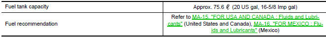
Fuel Tank
Standard and Limit
 Disassembly and assembly
FUEL LEVEL SENSOR UNIT
Disassembly and Assembly
Fuel Level Sensor Unit
Harness connectors
Fuel level sensor unit
Fuel tank temperature sensor
Float arm assembly
Disass ...
 Exhaust system
...
Other materials:
Daytime running light system
Wiring Diagram
...
Active trace control
The Integrated Dynamics-control Module is an
electric control module that includes the following
functions:
Active Trace Control
Active Engine Brake
Active Ride Control
This system senses driving based on the driver's
steering and acceleration/braking patterns, and
controls brake pres ...
ADP branch line circuit
Diagnosis Procedure
1.CHECK CONNECTOR
Turn the ignition switch OFF.
Disconnect the battery cable from the negative
terminal.
Check the following terminals and connectors
for damage, bend and loose connection (unit side and connector
side).
...
Nissan Maxima Owners Manual
- Illustrated table of contents
- Safety-Seats, seat belts and supplemental restraint system
- Instruments and controls
- Pre-driving checks and adjustments
- Monitor, climate, audio, phone and voice recognition systems
- Starting and driving
- In case of emergency
- Appearance and care
- Do-it-yourself
- Maintenance and schedules
- Technical and consumer information
Nissan Maxima Service and Repair Manual

0.007