Nissan Maxima Service and Repair Manual: Vacuum lines
Exploded View
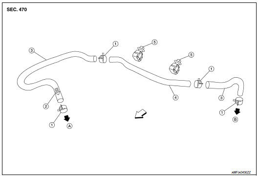
- Clamp
- Installation arrow
- Vacuum hose
- Vacuum pipe
- Clip
- To intake manifold
- To brake booster
 Front
Front
Removal and Installation
REMOVAL
- Disconnect the vacuum hose from the brake booster.
- Disconnect the vacuum hose from the intake manifold.
- Release the clips and remove the vacuum pipe with the vacuum hoses attached.
- Remove the vacuum hoses from the vacuum pipe.
INSPECTION AFTER REMOVAL
Visual Inspection
Check for correct installation, damage and deterioration of the vacuum hoses and pipe.
Valve Air-tightness Check
- Connect a suitable tool (hand vacuum pump) at each end of the vacuum hose to inspect the check valve operation.
- Replace the vacuum hose component or check valve if out of specification
INSTALLATION
Installation is in the reverse order of removal.
CAUTION:
- Because the vacuum hose contains a check valve, the vacuum hose must be installed in the correct position for proper operation. Refer to the stamp on the end of the vacuum hose to confirm correct installation. The brake booster will not operate normally if the vacuum hose with the check valve is installed in the wrong direction.
- Insert the vacuum pipe into the vacuum hose at least 24 mm (0.94 in) as shown.
- Do not use lubricating oil during installation.
 Brake booster
Exploded View
Master cylinder assembly
Brake booster
Brake pedal
Lock nut
Gasket
Removal and installation
NOTE:
When removing components such as hoses, tubes/lines, etc., cap ...
 Front disc brake
Exploded View of Brake Pads
Inner shim cover
Inner shim
Inner pad
Outer pad
Outer shim
Outer shim cover
Anti-rattle clips
Pad retainers
Molykote AS-880N grease
Mo ...
Other materials:
Answer back horn feature
If desired, the answer back horn feature can be
deactivated using the Intelligent Key. When it is
deactivated and the LOCK
button is
pushed, the hazard indicator lights flash twice.
When the UNLOCK button is pushed,
neither
the hazard indicator lights nor the horn operates.
NO ...
Lifting sensor (front)
Description
The lifting sensor (front) is installed to the seat frame.
The pulse signal is input to the driver seat control unit when the
lifting (front) is operated.
The driver seat control unit counts the pulse and calculates the lifting
(front) amount of the seat.
Component Funct ...
Tire labeling
Example
Federal law requires tire manufacturers to
place standardized information on the
sidewall of all tires. This information identifies
and describes the fundamental
characteristics of the tire and also provides
the tire identification number (TIN)
for safety standard certification. The ...
Nissan Maxima Owners Manual
- Illustrated table of contents
- Safety-Seats, seat belts and supplemental restraint system
- Instruments and controls
- Pre-driving checks and adjustments
- Monitor, climate, audio, phone and voice recognition systems
- Starting and driving
- In case of emergency
- Appearance and care
- Do-it-yourself
- Maintenance and schedules
- Technical and consumer information
Nissan Maxima Service and Repair Manual

0.0081