Nissan Maxima Service and Repair Manual: Brake booster
Exploded View
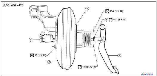
- Master cylinder assembly
- Brake booster
- Brake pedal
- Lock nut
- Gasket
Removal and installation
NOTE: When removing components such as hoses, tubes/lines, etc., cap or plug openings to prevent fluid from spilling.
REMOVAL
- Release the fuel pressure. Refer to EC-592, "Inspection".
- Disconnect the battery negative terminal. Refer to PG-67, "Exploded View".
- Remove the engine room cover. Refer to EM-23, "Removal and Installation".
- Remove the air cleaner and air duct. Refer to EM-24, "Removal and Installation".
- Remove cowl top, cowl top extension LH and the lower cowl top extension brace. Refer to EXT-20, "Exploded View".
- Disconnect fuel line from engine, clip and main line and reposition out of the way.
- Remove master cylinder. Refer to BR-24, "Removal and Installation".
- Disconnect vacuum hose from brake booster.
- Remove instrument lower panel LH. Refer to IP-10, "Exploded View".
- Disconnect the harness connector from the accelerator pedal.
- Remove snap pin and clevis pin from inside vehicle.
- Disconnect the steering column upper joint and reposition it out of the way.
- Disconnect the harness connectors from the ASCD cancel switch and stop lamp switch.
- Remove nuts on brake booster and brake pedal assembly, then remove brake pedal. Refer to BR-18, "Exploded View".
- Remove brake booster from dash panel on engine room side.
CAUTION: Be careful not to deform or bend brake tube while removing brake booster. - Remove the brake booster gasket.
INSTALLATION
CAUTION:
- Be careful not to deform or bend brake tube while installing brake booster.
- Replace clevis pin if it is damaged.
- Do not damage brake booster stud bolt threads. If brake booster is tilted during installation, the dash panel may damage the threads.
- Loosen lock nut to adjust input rod length (B) to the specified value as shown.
Input rod length (B) : Refer to BR-46, "Brake Booster".
- After adjusting input rod length (B), temporarily tighten the lock
nut to install the booster assembly. At this time, make sure that a
gasket between booster assembly and dash panel is installed.
CAUTION: Always install gasket between brake booster and dash panel. - Install and connect brake pedal with clevis of input rod.
- Install brake pedal bracket nuts and tighten them to the specified torque. Refer to BR-18, "Exploded View".
- Connect the ASCD cancel switch and stop lamp switch harness connectors.
- Connect the steering column upper joint.
- Connect the accelerator pedal harness connector.
- Install instrument lower panel LH. Refer to IP-10, "Exploded View".
- Install vacuum hose into brake booster.
- Install master cylinder. Refer to BR-24, "Removal and Installation".
- Position fuel line and connect to engine, clip and main line.
- Install the air cleaner and air duct. Refer to EM-24, "Removal and Installation".
- Install the engine room cover. Refer to EM-23, "Removal and Installation".
- Install the cowl top, cowl top extension LH and the lower cowl top extension brace. Refer to EXT-20, "Exploded View".
- Connect the battery negative terminal. Refer to PG-67, "Exploded View".
- Adjust the brake pedal height, if necessary. Refer to PG-67, "Exploded View".
- Tighten lock nut of input rod to the specified torque. Refer to BR-26, "Exploded View".
- Refill new brake fluid and bleed air. Refer to BR-16, "Bleeding Brake System".
 Brake master cylinder
Exploded View
Reservoir cap
Oil strainer (blue)
Master cylinder assembly
Brake fluid level switch harness connector
O-ring
PBC (Poly Butyl Cuprysil) grease or
silicone-ba ...
 Vacuum lines
Exploded View
Clamp
Installation arrow
Vacuum hose
Vacuum pipe
Clip
To intake manifold
To brake booster
Front
Removal and Installation
REMOVAL
Disconnect the vacuum ...
Other materials:
B263D, B263E, B263F intake door motor
Description
COMPONENT DESCRIPTION
Intake Door Motor
The intake door motor (1) is attached to the blower unit.
It rotates so that air is drawn from inlets set by the A/C auto
amp.
Motor rotation is conveyed to a lever which activates the intake
door.
DTC Logic
DTC DETECTION L ...
Front fog lamp
System Diagram
System Description
BCM (Body Control Module) controls front fog lamp operation.
IPDM E/R (Intelligent Power Distribution Module Engine Room)
operates front fog lamp according to CAN communication signals from BCM.
Combination meter operates front fog lamp indicator accor ...
Tweeter
Description
The AV control unit sends audio signals to the BOSE speaker amp. The BOSE
speaker amp. amplifies the
audio signals before sending them to the tweeters using the audio signal
circuits.
Diagnosis Procedure
1.CONNECTOR CHECK
Check the AV control unit, BOSE speaker amp. and speaker ...
Nissan Maxima Owners Manual
- Illustrated table of contents
- Safety-Seats, seat belts and supplemental restraint system
- Instruments and controls
- Pre-driving checks and adjustments
- Monitor, climate, audio, phone and voice recognition systems
- Starting and driving
- In case of emergency
- Appearance and care
- Do-it-yourself
- Maintenance and schedules
- Technical and consumer information
Nissan Maxima Service and Repair Manual

0.0156