Nissan Maxima Owners Manual: Climate controlled seat switches (if so equipped)
The climate controlled seat warms up or cools down the front seat by blowing warm or cool air from under the surface of the seat. The climate control switch is located on the center console.
The climate controlled seat can be operated as follows: 1. Start the engine.
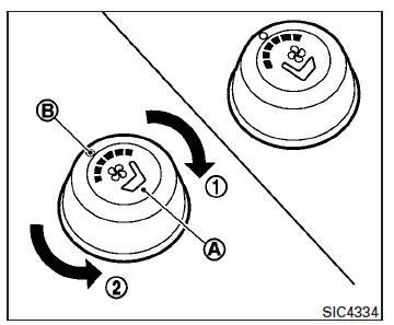
2. Turn the control knob A to the heat side 1 or the cool side 2 . The indicator light B on the control knob will illuminate.
3. Adjust the desired amount of air using the control knob. The climate controlled seat blower remains on low speed for approximately 60 seconds after turning the switch on or selecting the desired temperature.
4. When the vehicle's interior is warmed or cooled, or before you leave the vehicle, be sure to turn the control knob to the OFF (center) position. The indicator light B on the control knob goes off with the switch in the OFF (center) position.
To check the air filter for the climate controlled seat, it is recommended that you visit a NISSAN dealer.
WARNING
Do not use or allow occupants to use the climate controlled seats if you or the occupants cannot monitor seat temperatures or have an inability to feel pain in those body parts in contact with the seat.
Use of the climate controlled seats by such people could result in serious injury.
CAUTION
- The battery could run down if the climate control seat is operated while the engine is not running.
- Do not use the climate control seat for extended periods or when no one is using the seat.
- Do not put anything on the seat which insulates heat, such as a blanket, cushion, seat cover, etc. Otherwise, the seat may become overheated.
- Do not place anything hard or heavy on the seat or pierce it with a pin or similar objects. This may result in damage to the climate controlled seat.
- Any liquid spilled on the seat should be removed immediately with a dry cloth
- The climate controlled seat has an air filter. Do not operate the climate controlled seat without an air filter. This may result in damage to the system.
- When cleaning the seat, never use gasoline, benzine, thinner, or any similar materials.
- If any malfunctions are found or the climate controlled seat does not operate, turn the switch off and have the system checked. It is recommended that you visit a NISSAN dealer for this service.
 Horn
Horn
To sound the horn, push near the center pad of
the steering wheel.
WARNING
Do not disassemble the horn. Doing so
could affect proper operation of the
supplemental front air bag system. Tamperin ...
 Heated seat switches (if so equipped)
The front seats are warmed by built-in heaters.
1. Start the engine.
2. Push the LO or HI position of the switch, as
desired. The indicator light in the switch will
illuminate.
The heater ...
Other materials:
RCTA system operation
1. Side BSW/RCTA Indicator Light
2. BSW/RCTA Indicator
The RCTA system can help alert the driver of an
approaching vehicle when the driver is backing
out of a parking space.
When the shift position is in R (Reverse) and the
vehicle speed is less than approximately 5 mph
(8 km/h), the RC ...
AV control unit
Removal and Installation
AV control unit
AV control unit bracket LH
AV control unit bracket RH
A/C auto amp.
Cluster lid C (with A/C and AV switch assembly attached)
Clip
AV CONTROL UNIT
Removal
CAUTION: Before replacing AV control unit,
perform "READ CONFIGURATION" to s ...
Exterior rear
Rear window defroster switch
High-mounted stop light
Interior trunk lid release. Trunk lid
Exterior trunk lid release/request button. Rearview camera
Rear sonar sensors (if so equipped)
Replacing bulbs
Fuel-filler door. Fuel recommendation
Child safety rear door locks
R ...
Nissan Maxima Owners Manual
- Illustrated table of contents
- Safety-Seats, seat belts and supplemental restraint system
- Instruments and controls
- Pre-driving checks and adjustments
- Monitor, climate, audio, phone and voice recognition systems
- Starting and driving
- In case of emergency
- Appearance and care
- Do-it-yourself
- Maintenance and schedules
- Technical and consumer information
Nissan Maxima Service and Repair Manual

0.0066