Nissan Maxima Service and Repair Manual: Driver air bag module
Exploded View
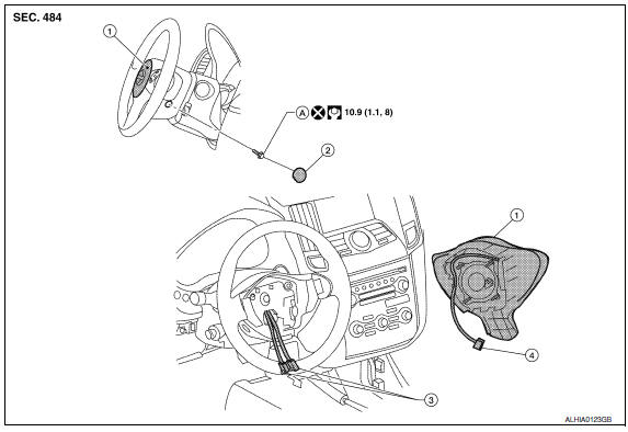
- Driver air bag module
- Side lid
- Driver air bag module harness connectors
- Steering wheel switch assembly connector
- Driver air bag module bolt
Removal and Installation
CAUTION:
- Before servicing, turn ignition switch OFF, disconnect both battery terminals and wait at least 3 minutes.
- Do not use air tools or electric tools for servicing.
- Always work from the side of air bag module. Do not work from the front of it.
- Always place air bag module with pad side facing upward.
- Do not cause impact to the air bag module by dropping etc. Replace the air bag module if it has been dropped or sustained an impact.
REMOVAL
- Disconnect the negative and positive battery terminals, then wait at least 3 minutes. Refer to PG-67, "Removal and Installation (Battery)".
- Remove side lids, then remove the driver air bag module bolts (LH/RH).
- Disconnect the harness connectors from the driver air bag module.
- For installing/removing direct-connect SRS harness connectors.
Refer to SRC-9, "SRS Component Connectors".
- Disconnect the steering wheel switch assembly harness connector.
Then remove driver air bag module from steering wheel.
- Remove the steering wheel switch assembly from driver air bag module. Refer to AV-81, "Removal and Installation".
INSTALLATION
CAUTION: Do not use old bolts after removal; replace with new bolts.
- Attach steering wheel switch assembly to driver air bag module.
- Route the driver air bag module harness through attachment hook on steering wheel.
- Place the driver air bag module near the steering wheel and attach harness connectors (A).
- Lift the driver air bag module while rotating counterclockwise into position over steering wheel.
- Pushing upward into place, position the steering wheel switch assembly harness along the upper edge and install the driver air bag module into the steering wheel.
- Make sure that the steering wheel switch assembly harness is routed above the center of the driver air bag module inflator (1) as shown (B), and is not routed so it is pinched between the driver air bag module inflator (1) and steering column shaft threads as shown (A).
CAUTION:
- Make sure the steering switch harness is correctly routed above the center of the driver air bag module inflator (1) as shown (B), and NOT incorrectly routed across the driver air bag module inflator as shown (A).
- Be careful not to damage or pinch the harness while installing.
- Tighten the driver air bag module bolts after centering the holes between the driver air bag module and the steering wheel horn contact bracket. If the holes are misaligned, the bolt threads may become damaged and the module will not install securely.
- Install the driver air bag module bolts.
CAUTION:
- After the work is completed, make sure no system malfunction is detected by air bag warning lamp.
- In case a malfunction is detected by the air bag warning lamp, reset by the self-diagnosis function and delete the memory by CONSULT.
- If a malfunction is still detected after the above operation,
perform self-diagnosis to repair malfunctions.
Refer to SRC-12, "SRS Operation Check".

 Spiral cable
Removal and Installation
CAUTION:
Before servicing, turn ignition switch OFF, disconnect both
battery terminals and wait at least 3 minutes.
Do not use air tools or electric tools for serv ...
Other materials:
Moving Object Detection (MOD) (if so equipped)
1. CAMERA button
WARNING
Failure to follow the warnings and instructions
for proper use of the Moving
Object Detection system could result in
serious injury or death.
The MOD system is not a substitute for
proper vehicle operation and is not designed
to prevent contact with obje ...
Recommended fluids/lubricants and capacities
The following are approximate capacities. The actual refill capacities may
be slightly different. When refilling, follow the procedure
described in the "Do-it-yourself" section to determine the proper refill
capacity.
...
Main line between A-bag and ABS circuit
Diagnosis Procedure
1.CHECK CONNECTOR
Turn the ignition switch OFF.
Disconnect the battery cable from the negative terminal.
Check the following terminals and connectors for damage, bend and
loose connection (connector side
and harness side).
Harness connector M1
Harness connect ...
Nissan Maxima Owners Manual
- Illustrated table of contents
- Safety-Seats, seat belts and supplemental restraint system
- Instruments and controls
- Pre-driving checks and adjustments
- Monitor, climate, audio, phone and voice recognition systems
- Starting and driving
- In case of emergency
- Appearance and care
- Do-it-yourself
- Maintenance and schedules
- Technical and consumer information
Nissan Maxima Service and Repair Manual

0.0054