Nissan Maxima Service and Repair Manual: ECU diagnosis information
DIAGNOSIS SENSOR UNIT
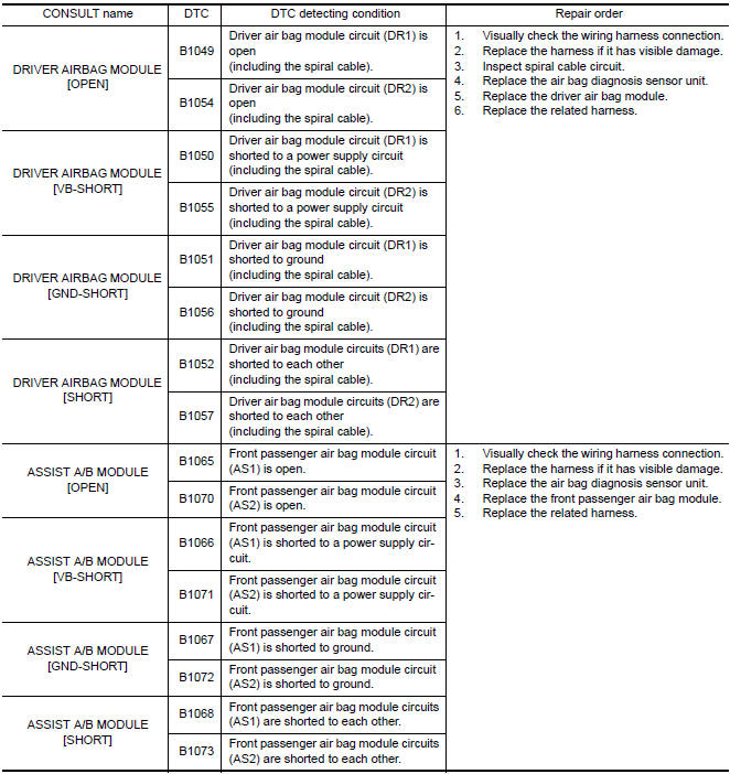
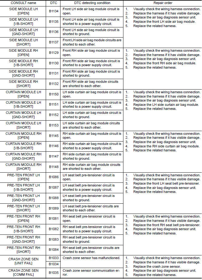
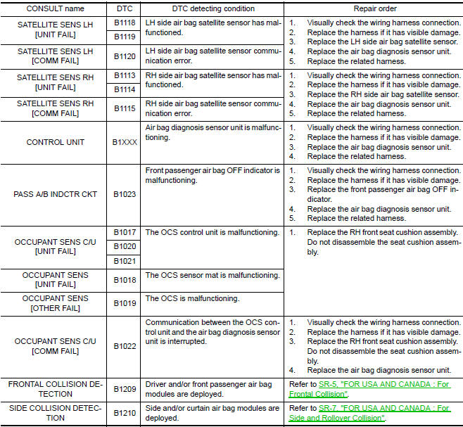
Trouble Diagnosis with CONSULT
DIAGNOSTIC CODE CHART
NOTE:
Follow the procedures in numerical
order when repairing malfunctioning parts. Confirm whether malfunction is
eliminated using air bag warning lamp or CONSULT each time repair is finished.
If malfunction is still
observed, proceed to the next step. When malfunction
is eliminated, further repair work is not required.
Trouble Diagnosis without CONSULT
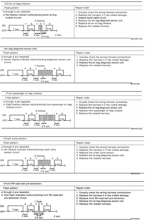
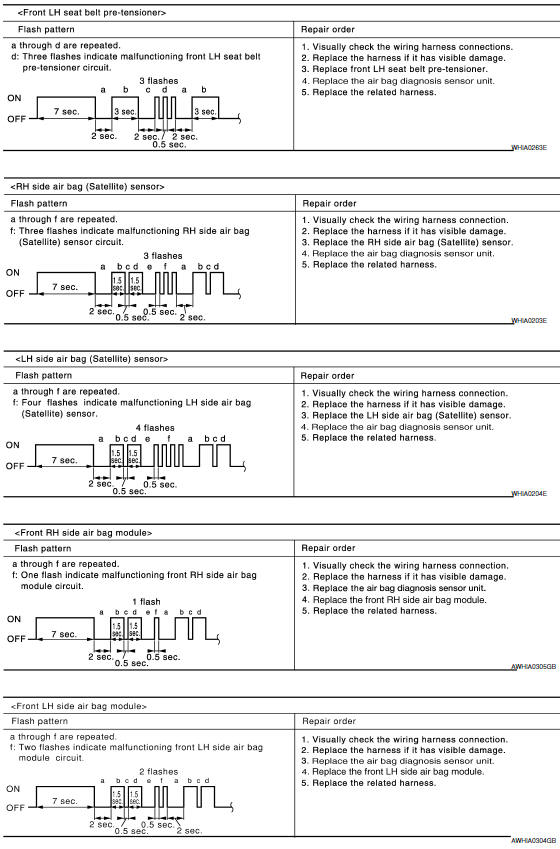
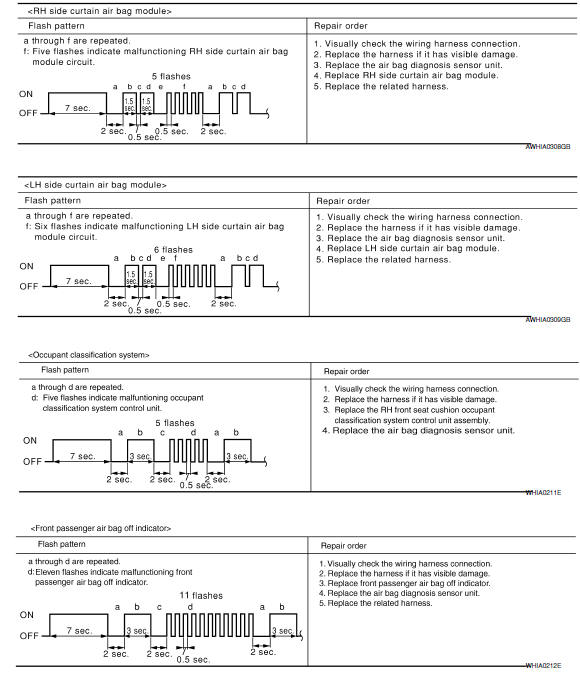
WARNING LAMP FLASH CODE CHART
NOTE:
Follow the procedures in numerical
order when repairing malfunctioning parts. Confirm whether malfunction is
eliminated using air bag warning lamp each time repair is finished. If
malfunction is still observed, proceed to
the next step. When malfunction is
eliminated, further repair work is not required.
 B1209 - B1210 collision detection
Description
DTC B1209 - B1210 COLLISION DETECTION
The air bag diagnosis sensor unit will set this DTC if it has detected a
collision which has resulted in a frontalor side deployment of one or mor ...
 Wiring diagram
SRS AIR BAG CONTROL SYSTEM
Wiring Diagram - For Mexico
Wiring Diagram - Except Mexico
...
Other materials:
Front fog lamp
Exploded View
Front bumper fascia
Front fog lamp
Front fog lamp bracket
Clip
Spring nuts
Removal and Installation
FRONT FOG LAMP
Removal
Remove the front bumper fascia. Refer to EXT-16, "Removal and
Installation".
Disconnect the harness connector from the fog lam ...
Combination switch input circuit
Diagnosis Procedure
1. CHECK INPUT 1 - 5 SYSTEM CIRCUIT FOR OPEN
Turn the ignition switch OFF.
Disconnect the BCM and combination switch.
Check continuity between BCM harness connector and combination
switch harness connector.
2. CHECK INPUT 1 - 5 SYSTEM CIRCUIT FOR SHORT
...
Children need adults to help protect them.
They need to be properly restrained.
In addition to the general information in this
manual, child safety information is available from
many other sources, including doctors, teachers,
government traffic safety offices, and community
organizations. Every child is different, so be sure
to lear ...
Nissan Maxima Owners Manual
- Illustrated table of contents
- Safety-Seats, seat belts and supplemental restraint system
- Instruments and controls
- Pre-driving checks and adjustments
- Monitor, climate, audio, phone and voice recognition systems
- Starting and driving
- In case of emergency
- Appearance and care
- Do-it-yourself
- Maintenance and schedules
- Technical and consumer information
Nissan Maxima Service and Repair Manual

0.0062