Nissan Maxima Service and Repair Manual: Periodic maintenance
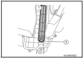
IN-CABIN MICROFILTER
Removal and Installation
REMOVAL

- Disengage the filter cover tab (1) by pushing up and pull out to remove the filter cover.
- Remove the in-cabin microfilter from the blower unit.
INSTALLATION
Installation is in the reverse order of removal.
 System description
AUTOMATIC AIR CONDITIONER SYSTEM
WITH COLOR DISPLAY
WITH COLOR DISPLAY : Switches And Their Control F
WITH COLOR DISPLAY : Discharge Air Flow
WITH MONOCHROME DISPLAY
WITH MONOCHROME DISPLAY : ...
Other materials:
Unit removal and installation
TRANSAXLE ASSEMBLY
Exploded View
Air breather hose
CVT fluid level gauge
CVT fluid charging pipe
O-ring
Copper sealing washer
Fluid cooler tube
Transaxle assembly
A. Refer to INSTALLATION.
...
Rear lower link & coil spring
Removal and Installation
Removal
Remove the rear wheel and tire using power tool. Refer to WT-60,
"Adjustment".
Loosen the rear lower link adjusting bolt and nut at the rear
suspension member.
Support the rear lower link with a suitable jack.
Support the rear axle housing with a ...
P0196 EOT sensor
Description
The engine oil temperature sensor is used to detect the engine oil
temperature. The sensor modifies a voltage signal from the ECM.
The modified signal returns to the ECM as the engine oil temperature
input. The sensor uses a thermistor which is sensitive to the
change in te ...
Nissan Maxima Owners Manual
- Illustrated table of contents
- Safety-Seats, seat belts and supplemental restraint system
- Instruments and controls
- Pre-driving checks and adjustments
- Monitor, climate, audio, phone and voice recognition systems
- Starting and driving
- In case of emergency
- Appearance and care
- Do-it-yourself
- Maintenance and schedules
- Technical and consumer information
Nissan Maxima Service and Repair Manual
0.0219

