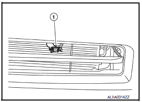
Nissan Maxima Service and Repair Manual: Ambient sensor
Removal and Installation
REMOVAL
- From under the vehicle, disconnect the harness connector from the ambient sensor.
- Release the ambient sensor clip and remove the ambient sensor (1).

INSTALLATION
Installation is in the reverse order of removal.
 Control unit
Removal and Installation
A/C SWITCH ASSEMBLY
Removal
Remove cluster lid D. Refer to IP-10, "Exploded View".
Remove the A/C switch assembly from cluster lid D.
Installation
Instal ...
 In-vehicle sensor
Removal and Installation
REMOVAL
Remove the instrument lower panel LH. Refer to IP-19, "Removal and
Installation".
Remove the in-vehicle sensor screw and the in-vehicle sensor. ...
Other materials:
Vehicle security system
Your vehicle has two types of security systems:
Vehicle security system
NISSAN Vehicle Immobilizer System
The vehicle security system provides visual and
audible alarm signals if someone opens the
doors, trunk, or hood when the system is armed. It
is not, however, a motion detection ...
Excessive ABS function operation frequency
Diagnosis Procedure
1.CHECK START
Check front and rear brake force distribution using a brake tester.
2.CHECK FRONT AND REAR AXLE
Make sure that there is no excessive play in the front and rear axles.
3.CHECK WHEEL SENSOR AND SENSOR ROTOR
Check the following:
Wheel sensor installation for ...
Refrigerant pressure sensor
Description
The refrigerant pressure sensor is installed at the condenser of the air
conditioner system. The sensor uses an
electrostatic volume pressure transducer to convert refrigerant pressure to
voltage. The voltage signal is sent
to ECM, and ECM controls cooling fan system.
Compo ...
Nissan Maxima Owners Manual
- Illustrated table of contents
- Safety-Seats, seat belts and supplemental restraint system
- Instruments and controls
- Pre-driving checks and adjustments
- Monitor, climate, audio, phone and voice recognition systems
- Starting and driving
- In case of emergency
- Appearance and care
- Do-it-yourself
- Maintenance and schedules
- Technical and consumer information
Nissan Maxima Service and Repair Manual
0.0056
