Nissan Maxima Service and Repair Manual: Door lock and unlock switch
DRIVER SIDE
DRIVER SIDE : Description
Transmits door lock/unlock operation to BCM.
DRIVER SIDE : Component Function Check
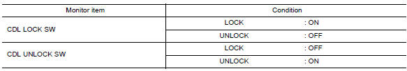
1. CHECK FUNCTION
With CONSULT
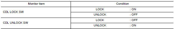
Check CDL LOCK SW, CDL UNLOCK SW in Data Monitor mode with CONSULT
DRIVER SIDE : Diagnosis Procedure
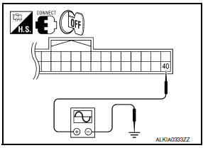
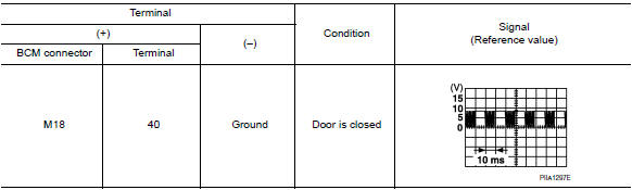
1. CHECK POWER WINDOW SWITCH OUTPUT SIGNAL
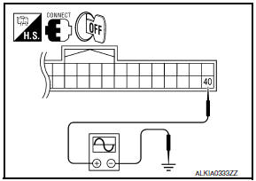
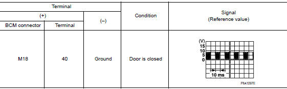
- Read voltage signal between BCM connector and ground with oscilloscope when door lock and unlock switch (driver side) is turned "LOCK" or "UNLOCK".
- Check that signals which are shown in the figure below can be detected during 10 second just after door lock and unlock switch (driver side) is turned to "LOCK" or "UNLOCK".
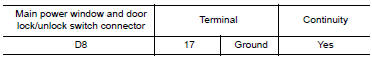
2. CHECK POWER WINDOW SWITCH GROUND
- Turn ignition switch OFF.
- Disconnect main power window and door lock/unlock switch connector.
- Check continuity between main power window and door lock/ unlock switch connector and ground.
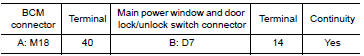
3. CHECK POWER WINDOW SERIAL LINK CIRCUIT
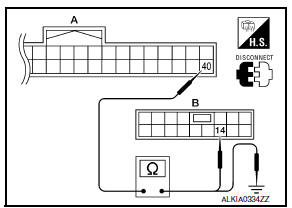
- Disconnect BCM connector.
- Check continuity between BCM connector and main power window and door lock/unlock switch connector.
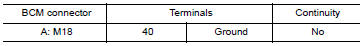
- Check continuity between BCM connector and ground.
4. CHECK INTERMITTENT INCIDENT
DRIVER SIDE : Special Repair Requirement
INITIALIZATION PROCEDURE
- Disconnect battery negative terminal or main power window and door lock/unlock switch. Reconnect it after a minute or more.
- Turn ignition switch ON.
- Operate power window switch to fully open the window. (This operation is unnecessary if the window is already fully open)
- Continue pulling the power window switch UP (AUTO-UP operation). Even after glass stops at fully closed position, keep pulling the switch for 4 seconds or more.
- Inspect anti-pinch function.
CHECK ANTI-PINCH FUNCTION
- Fully open the door window.
- Place a piece of wood near fully closed position.
- Close door glass completely with AUTO-UP.
- Check that glass lowers for approximately 150 mm (5. 91 in) or 2 seconds without pinching piece of wood and stops.
- Check that glass does not rise when operating the main power window and door lock/unlock switch while lowering.
CAUTION:
- Do not check with hands and other parts of the body because they may be pinched. Do not get pinched.
- Check that AUTO-UP operates before inspection when system initialization is performed.
- It may switch to fail-safe mode if open/close operation is performed continuously. Perform initial setting in that situation. Refer to PWC-53, "Fail Safe", PWC-56, "Fail Safe" or PWC-78, "Fail Safe".
- Perform initial setting when auto-up operation or anti-pinch function does not operate normally.
- Finish initial setting. Otherwise, next operation cannot be done.
- Auto-up operation
- Anti-pinch function
- Retained power operation when ignition switch is OFF.
PASSENGER SIDE
PASSENGER SIDE : Description
Transmits door lock/unlock operation to BCM.
PASSENGER SIDE : Component Function Check
1. CHECK FUNCTION
With CONSULT
Check CDL LOCK SW, CDL UNLOCK SW in Data Monitor mode with CONSULT
PASSENGER SIDE : Diagnosis Procedure
1. CHECK POWER WINDOW SWITCH OUTPUT SIGNAL
- Read voltage signal between BCM connector and ground with oscilloscope when door lock and unlock switch (passenger side) is turned to "LOCK" or "UNLOCK".
- Check that signals which are shown in the figure below can be detected during 10 second just after door lock and unlock switch (passenger side) is turned to "LOCK" or "UNLOCK".
2. CHECK POWER WINDOW SWITCH GROUND
- Turn ignition switch OFF.
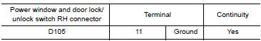
- Disconnect power window and door lock/unlock switch RH connector.
- Check continuity between front power window switch (passenger side) connector and ground.
3. CHECK POWER WINDOW SERIAL LINK CIRCUIT
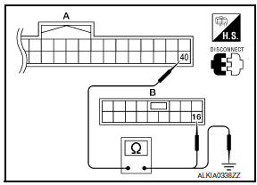
- Disconnect BCM connector.
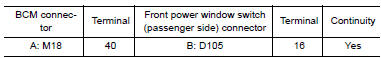
- Check continuity between BCM connector and front power window switch (passenger side) connector.
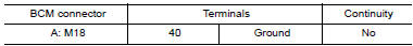
- Check continuity between BCM connector and ground.
4. CHECK INTERMITTENT INCIDENT
PASSENGER SIDE : Special Repair Requirement
INITIALIZATION PROCEDURE
- Disconnect battery negative terminal or main power window and door lock/unlock switch. Reconnect it after a minute or more.
- Turn ignition switch ON.
- Operate power window switch to fully open the window. (This operation is unnecessary if the window is already fully open)
- Continue pulling the power window switch UP (AUTO-UP operation). Even after glass stops at fully closed position, keep pulling the switch for 4 seconds or more.
- Inspect anti-pinch function.
CHECK ANTI-PINCH FUNCTION
- Fully open the door window.
- Place a piece of wood near fully closed position.
- Close door glass completely with AUTO-UP.
- Check that glass lowers for approximately 150 mm (5. 91 in) or 2 seconds without pinching piece of wood and stops.
- Check that glass does not rise when operating the main power window and door lock/unlock switch while lowering.
CAUTION:
- Do not check with hands and other parts of the body because they may be pinched. Do not get pinched.
- Check that AUTO-UP operates before inspection when system initialization is performed.
- It may switch to fail-safe mode if open/close operation is performed continuously. Perform initial setting in that situation. Refer to PWC-53, "Fail Safe", PWC-56, "Fail Safe" or PWC-78, "Fail Safe".
- Perform initial setting when auto-up operation or anti-pinch function does not operate normally.
- Finish initial setting. Otherwise, next operation cannot be done.
- Auto-up operation
- Anti-pinch function
- Retained power operation when ignition switch is OFF.
 Door switch
Description
Detects door open/close condition.
Component Function Check
1. CHECK FUNCTION
With CONSULT
Check door switches DOOR SW-DR, DOOR SW-AS, DOOR SW-RL, DOOR SW-RR in Data
Monitor mode
...
 Key slot
Description
Detects whether Intelligent Key is inserted.
Immobilizer antenna amp checks Intelligent Key transponder.
Component Function Check
1. CHECK FUNCTION
With CONSULT
Check KEY SW -SLO ...
Other materials:
P0335 CKP sensor (POS)
Description
The crankshaft position sensor (POS) is located on the oil pan facing
the gear teeth (cogs) of the signal plate. It detects the fluctuation of
the engine revolution.
The sensor consists of a permanent magnet and Hall IC.
When the engine is running, the high and low parts o ...
Outside key antenna
REAR BUMPER
REAR BUMPER : Removal and Installation
REMOVAL
Remove the rear bumper. Refer to EXT-17, "Removal and
Installation".
Disconnect harness connector (1) from the outside key antenna
(rear bumper) (2).
Remove the outside key antenna (rear bumper) screws (A) and
...
How to enable/disable the BSW system
Perform the following steps to enable or disable
the BSW system.
1. Press the button until
"Settings" displays
in the vehicle information display and
then press OK. Use the button
to
select "Driver Assistance". Then press the
OK button.
2. Select "Blind Spot" and press the ...
Nissan Maxima Owners Manual
- Illustrated table of contents
- Safety-Seats, seat belts and supplemental restraint system
- Instruments and controls
- Pre-driving checks and adjustments
- Monitor, climate, audio, phone and voice recognition systems
- Starting and driving
- In case of emergency
- Appearance and care
- Do-it-yourself
- Maintenance and schedules
- Technical and consumer information
Nissan Maxima Service and Repair Manual

0.006