Nissan Maxima Service and Repair Manual: Vehicle security system
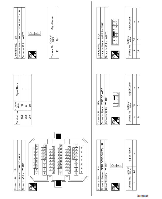
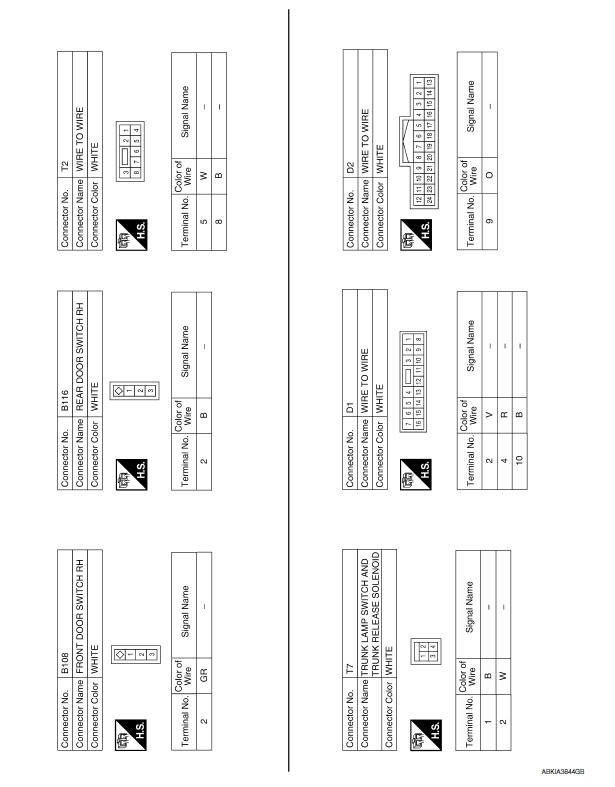
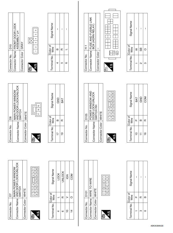
Wiring Diagram
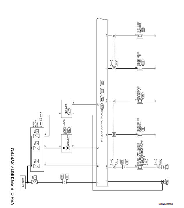
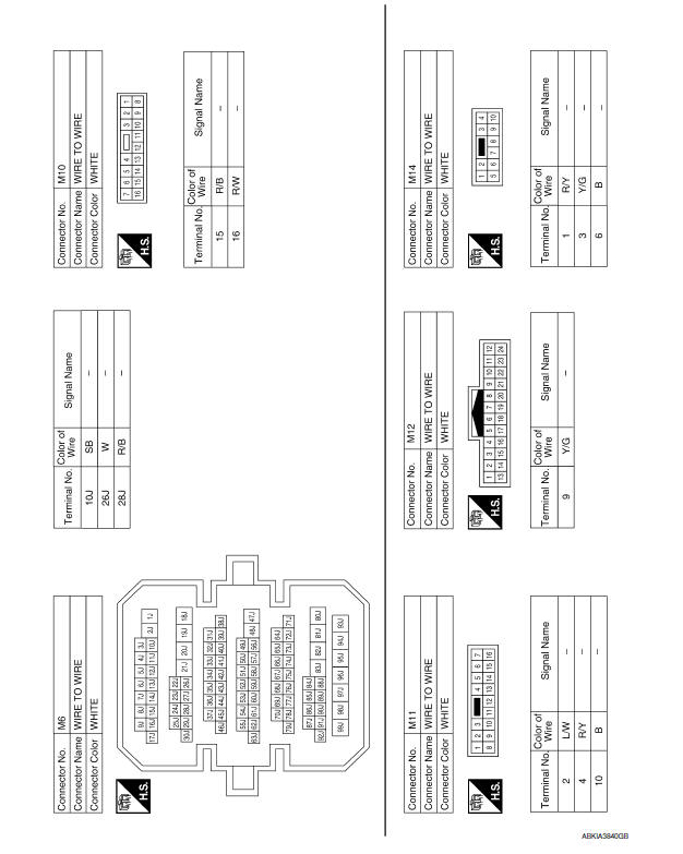
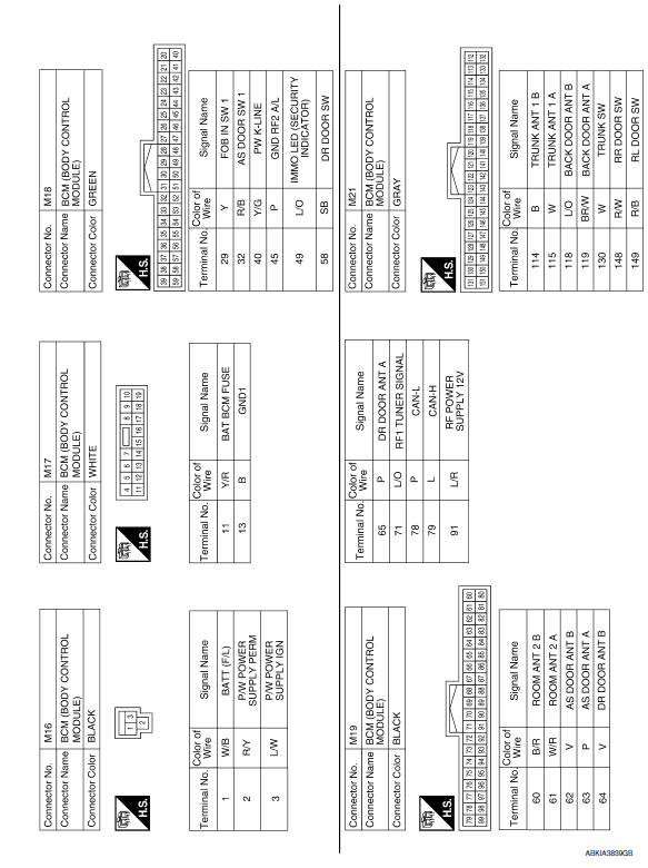
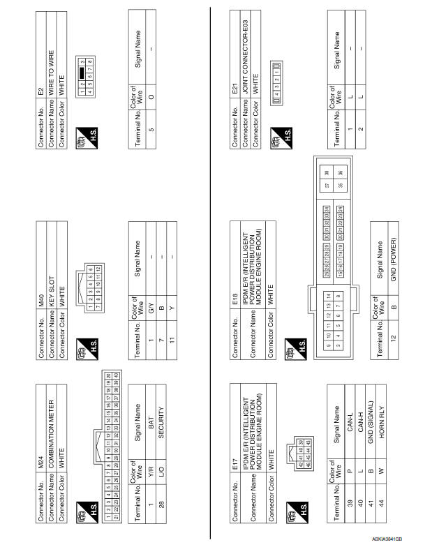
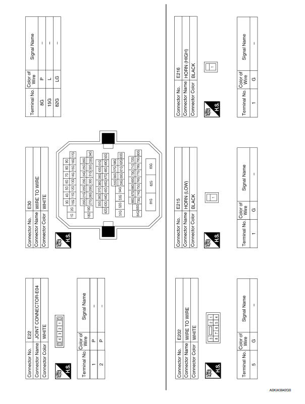
 NVIS
NVIS
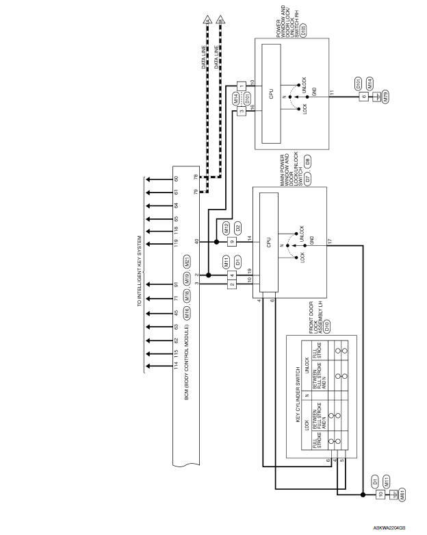
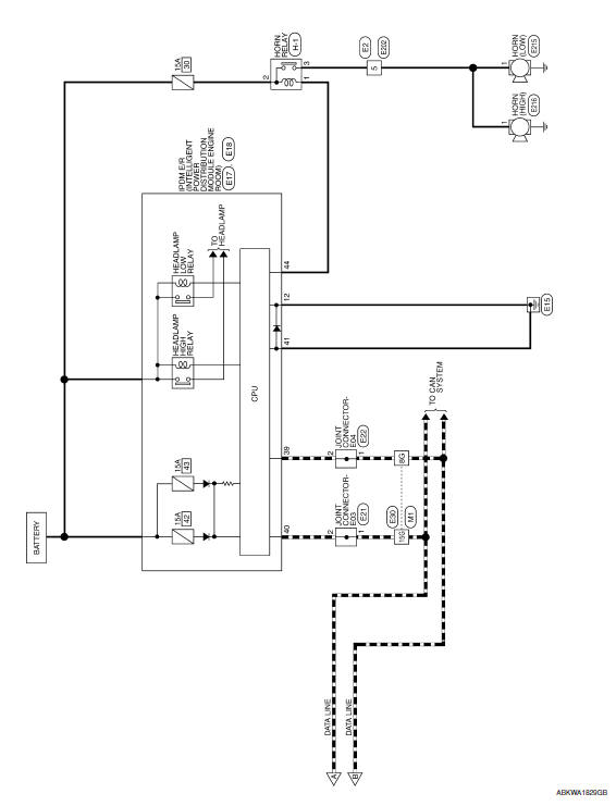
Wiring Diagram
...
 Intelligent key system/engine start function
Wiring Diagram
...
Other materials:
Antenna AMP
Removal and Installation
REMOVAL
Remove the rear pillar finisher RH. Refer to INT-27, "Exploded
View".
Detach the antenna amp. harness clip (A).
Disconnect the harness connectors (B) from the antenna amp.
(1).
Remove the antenna amp. screw (C) and the antenna amp. (1).
...
P0826 up and down shift SW
Description
Manual mode switch transmits signals (manual mode, not manual mode, shift up
and shift down) to combination
meter.
Paddle shifter transmits signals (shift up and shift down) to combination
meter. (With paddle shifter)
Combination meter transmits signals (manual mode, not manual ...
C1156 ST ANG sen com cir
Description
The steering angle sensor is connected to the ABS actuator and electric unit
(control unit) in addition to CAN
lines. CAN (Controller Area Network) is a serial communication line for real
time application. It is an on-vehicle
multiplex communication line with high data communica ...
Nissan Maxima Owners Manual
- Illustrated table of contents
- Safety-Seats, seat belts and supplemental restraint system
- Instruments and controls
- Pre-driving checks and adjustments
- Monitor, climate, audio, phone and voice recognition systems
- Starting and driving
- In case of emergency
- Appearance and care
- Do-it-yourself
- Maintenance and schedules
- Technical and consumer information
Nissan Maxima Service and Repair Manual

0.0066