Nissan Maxima Service and Repair Manual: Sunroof motor assembly
Referenc
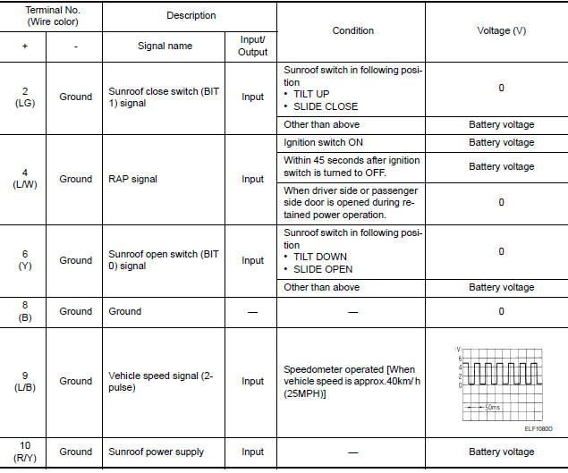
TERMINAL LAYOUT

PHYSICAL VALUES
 BCM (body control module)
Reference Value
NOTE: The Signal Tech II Tool (J-50190) can
be used to perform the following functions. Refer to the Signal Tech II User
Guide for additional information.
Activate and display ...
 Wiring diagram
SUNROOF SYSTEM
Wiring Diagram
...
Other materials:
Telescopic switch
Description
ADP steering switch (telescopic switch) is equipped to the steering column.
The operation signal is input to the automatic drive positioner control unit
when the telescopic switch is operated.
Component Function Check
1. CHECK FUNCTION
Select "TELESCO SW-FR", "TELESCO SW-RR" i ...
Warning function symptoms
Symptom Table
WARNING FUNCTION MALFUNCTION
NOTE:
Before performing the diagnosis in the following table, check
"WORK FLOW". Refer to DLK-9, "Work Flow".
Check that vehicle is under the condition shown in "Conditions
of vehicle" before starting diagnosis, and
check each sy ...
Wiring diagram
BCM (BODY CONTROL MODULE)
Wiring Diagram
...
Nissan Maxima Owners Manual
- Illustrated table of contents
- Safety-Seats, seat belts and supplemental restraint system
- Instruments and controls
- Pre-driving checks and adjustments
- Monitor, climate, audio, phone and voice recognition systems
- Starting and driving
- In case of emergency
- Appearance and care
- Do-it-yourself
- Maintenance and schedules
- Technical and consumer information
Nissan Maxima Service and Repair Manual

0.0062