Nissan Maxima Service and Repair Manual: Washer motor circuit
Diagnosis Procedure
1. CHECK FRONT WASHER MOTOR FUSE
- Turn the ignition switch OFF.
- Check that the following fuse is not blown.

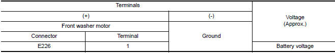
2. CHECK FRONT WASHER MOTOR POWER SUPPLY
- Disconnect front washer motor.
- Turn ignition switch ON.
- Check voltage between front washer motor harness connector and ground.
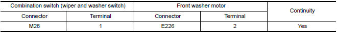
3. CHECK FRONT WASHER MOTOR CIRCUIT CONTINUITY
- Turn the ignition switch OFF.
- Disconnect combination switch (wiper and washer switch).
- Check continuity between combination switch (wiper and washer
switch) harness connector and front
washer motor.
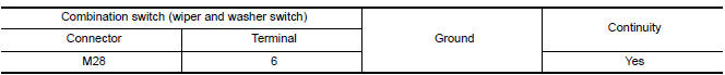
4. CHECK WIPER AND WASHER SWITCH GROUND CIRCUIT
Check continuity between combination switch (wiper and washer switch) harness connector and ground.
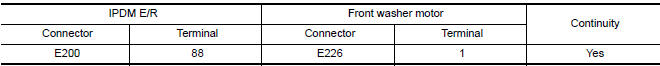
5. CHECK FRONT WASHER MOTOR OPEN CIRCUIT
- Turn the ignition switch OFF.
- Disconnect IPDM E/R.
- Check continuity between IPDM E/R harness connector and front washer motor.
6. CHECK WIPER AND WASHER SWITCH
Check wiper and washer switch.
 Washer switch
Description
Washer switch is integrated with combination switch (wiper and washer
switch).
Combination switch (wiper and washer switch) supplies ground and fuse #
38 from the IPEM E/R supp ...

Other materials:
C1147, C1148, C1149, C1150 USV/HSV line
Description
USV1, USV2 (CUT VALVE)
The cut valve shuts off the normal brake fluid path from the master cylinder,
when VDC/TCS is activated.
HSV1, HSV2 (SUCTION VALVE)
The suction valve supplies the brake fluid from the master cylinder to the
pump, when VDC/TCS is activated.
DTC Logic
DTC D ...
Diagnosis system (TCM)
CONSULT Function
FUNCTION
CONSULT can display each diagnostic item using the diagnostic test modes
shown following.
WORK SUPPORT MODE
Display Item List
Engine Brake Adjustment
CAUTION:
Mode of "+1""0""−1""−2""OFF" can be selected by touching "UP"or
"DOWN" on CONSULT screen ...
P0776 pressure control solenoid B
Description
The secondary pressure solenoid valve regulates the secondary pressure to
suit the driving condition in
response to a signal sent from the TCM.
DTC Logic
DTC DETECTION LOGIC
DTC CONFIRMATION PROCEDURE
CAUTION:
Always drive vehicle at a safe speed.
NOTE:
Immediately after ...
Nissan Maxima Owners Manual
- Illustrated table of contents
- Safety-Seats, seat belts and supplemental restraint system
- Instruments and controls
- Pre-driving checks and adjustments
- Monitor, climate, audio, phone and voice recognition systems
- Starting and driving
- In case of emergency
- Appearance and care
- Do-it-yourself
- Maintenance and schedules
- Technical and consumer information
Nissan Maxima Service and Repair Manual

0.0057